Aller au contenu principal
  • Investisseurs
  • Partenaires
  • Billet de blog
  • Nous contacter
Précédent
  • United States
  • 中国
  • 日本
  • Brasil
  • СНГ
  • Deutschland
  • España
  • France
  • United Kingdom
  • Mexico
VIAVI Solutions
Précédent
  • United States
  • 中国
  • 日本
  • Brasil
  • СНГ
  • Deutschland
  • España
  • France
  • United Kingdom
  • Mexico
Search icon
    • Laboratoire et production
      • Laboratoire et production
        • Test RIC
        • Émulation d’applications
        • Automation and Orchestration
        • Émulation UE
        • Émulation Cloud UE
        • Émulation de cœur
        • Test du Coeur
        • Simulateur O-CU
        • Test O-CU
        • Test O-DU
        • Test O-RU
        • Validation de sécurité
        • Test en tant que service (TaaS)
        • Ethernet Test
        • Réseaux haut débit
        • Plateforme de test optique
      • Test de réseau de stockage
        • Test de réseau de stockage
        • Équipement de test PCIe
        • SAS et SATA
        • Fibre Channel, Ethernet, FCoE, NVMeoF
        • Test de protocoles
        • Systèmes de mise en condition et générateurs
        • Brouilleurs
    • Déploiement et maintenance de réseau
      • Déploiement et maintenance de réseau
        • Alignement et surveillance des antennes
        • Gestion des produits et des données
        • Installation et maintenance d’antenne-relais
        • Analyseur de câble et d’antenne
        • Chasse aux interférences
        • Analyse RF
      • Fibre
        • Fibre
        • Gestion des produits et des données
        • Atténuateurs
        • Taux d’erreurs binaire (BER)
        • Test cuivre, DSL, Wi-Fi et large bande
        • Test de DOCSIS
        • Testeurs de fibre optique
        • Ethernet Test
        • Réflectomètre optique et caractérisation de la fibre
        • Pinces à trafic
        • Inspection et nettoyage des connecteurs optiques
        • Localisateurs de défauts
        • Capteurs à fibre optique
        • Sources optiques pour fibres optiques
      • Fibre
        • Fibre
        • Test HFC
        • Équipement de test de câble ruban multifibres MPO
        • Multimètre optique
        • Photomètres
        • Analyseur de spectre optique
        • Réflectomètre optique OTDR
        • Tester les réseaux PON
        • Surveillance de la fibre optique
        • Tests et activation virtuels
        • AIOps
        • Core Network Assurance
        • Assurance - Ethernet
        • RAN Assurance
        • Surveillance de la fibre optique
      • Assurance - Service
        • Assurance - Service
        • Assurance réseaux 5G
        • AIOps
        • Assurance de service pour la fibre optique
        • Assurance de service pour HFC/Câble
        • Transport Assurance
      • Laboratoire et production
        • Laboratoire et production
        • Automation and Orchestration
        • Émulation Cloud UE
        • Émulation de cœur
        • Test du Coeur
        • Simulateur O-CU
        • Test O-CU
        • Test O-DU
        • Test O-RU
        • Test RIC
        • Validation de sécurité
        • Gestion des produits et des données
        • Network APIs
        • Surveillance de la fibre optique
        • Tests et activation virtuels
        • AIOps
        • Assurance - Ethernet
        • Surveillance de la fibre optique
    • Réseaux télécom ferroviaires et critiques
      • Réseaux télécom ferroviaires et critiques
      • Drive Test
      • ERTMS and FRMCS Monitoring
      • Mission Critical Assurance
      • Railway Cybersecurity
      • Visibilité sur les performances et les menaces
        • Visibilité sur les performances et les menaces
        • Expérience de l’utilisateur final
        • Collecte - Flux enrichis
        • Analyse des paquets
        • Collecte - Capture des paquets
        • Collecte - Métadonnées de paquets
      • Test et certification
        • Test et certification
        • Taux d’erreurs sur les bits
        • Ethernet Test
        • Pinces à trafic
        • Inspection et nettoyage des connecteurs optiques
        • Capteurs à fibre optique
        • Équipement de test de câble ruban multifibres MPO
        • Photomètres
    • Services mobiles terrestres et radio militaires
      • Services mobiles terrestres et radio militaires
      • Communications Service Monitors
      • Test radio mobile terrestre
      • Test radio militaire
      • Instruments modulaires
      • Radio et systèmes logiciels
    • Avionique
      • Avionique
      • Conformité ADS-B
      • Kits et interfaces de tests de quantité de carburant pour avion
      • Coupleurs d’antennes
      • Équipement de mesure de distance (DME)
      • Fibre optique et avionique
      • Simulation GPS
      • Avionique militaire
      • Instruments modulaires
      • Navigation et communication
      • Radioaltimètres (RADALT)
      • Systèmes d’équipements de tests automatiques de fréquence radio (RF ATE)
      • Système de navigation aérienne tactique (TACAN)
      • Système d’alerte de trafic et d’évitement de collision (TCAS)
      • Transpondeur et interrogateur
    • Position, Navigation et Synchronisation
      • Position, Navigation et Synchronisation
      • GNSS Disciplined Oscillators
      • GNSS/GEO/LEO Grandmaster Clocks
      • GNSS/GEO/LEO Receiver Modules
      • GPS Simulator
      • RF Transcoder
      • Resilient GEO/LEO Timing Services
    • Custom Optics and Pigments
      • Custom Optics and Pigments
      • Produits optiques personnalisés
        • Produits optiques personnalisés
        • Filtres optiques personnalisés
        • Optique de mise en forme de la lumière
        • Spectromètres MicroNIR
      • Pigments
        • Pigments
        • Protection de la marque
        • Pigments ChromaFlair
        • Pigments de sécurité
        • Pigments SpectraFlair
      • 800G Ethernet Testing
      • Automotive Ethernet Device and Network Testing
      • Cybersecurity Test and Validation
      • Ethernet and IP Testing
      • Network Impairment and Emulation Testing
      • Radio Frequency (RF) and Wi-Fi Channel Emulation
      • TestCenter
      • Time-Sensitive Networking Testing
      • Timing and Synchronization Testing
    • Tous les produits
      • Tous les produits
      • Tous les produits
      • Produits par famille
      • Produits obsolètes
    • Services
      • Services
      • Contrats d’assistance et de maintenance
      • Produits remis à neuf
      • Réparation et étalonnage
      • Maintenance système et contrats
      • Formation
      • VIAVI Automated Lab-as-a-Service for Open RAN (VALOR)
      • Commander des services
      • Réseaux mobiles
        • Réseaux mobiles
        • Solutions 5G
        • 5G Security
        • Synchronisation temps et phase
        • 6G Forward
        • AIOps
        • Automated Lab-as-a-Service for Open RAN
        • Installation des antennes-relais
        • Tests basés sur le cloud
        • Chasse aux interférences
        • MU-MIMO Test
        • Network Digital Twin
        • Réseaux non terrestres (NTN)
        • Open RAN (O-RAN)
        • Réseaux privés 5G
        • RAN Intelligence Solutions
      • Liaisons filaires
        • Liaisons filaires
        • AIOps
        • DWDM
        • Test d’activation de service Ethernet
        • Fiber Construction
        • Surveillance des fibres
        • Fiber Network Solutions
        • Détection par fibre optique
        • FTTx
        • HFC Network Test
        • Tests des connecteurs MPO
        • Solutions PON
        • Rural Broadband
        • Automatisation des procédures de test (Test Process Automation, ou TPA)
        • Opérations des réseaux de transport
        • Hyperscale
        • Interconnexion de datacenter à datacenter
        • Tests des connecteurs MPO
        • Certification de la fibre optique de niveau 1 (de base)
        • Certification de la fibre optique de niveau 2 (étendue)
    • Équipementiers réseau
      • Équipementiers réseau
        • 5G Security
        • 5G Network Equipment Manufacturers
        • 6G Forward
        • Capacités d'analyse
        • Tests basés sur le cloud
        • Non-Terrestrial Networks
        • Open RAN Security Test
        • Réseaux privés 5G
        • Coherent Optics Testing
        • Déploiement sur le terrain
        • Production évolutive
        • Introduction de technologies et de services
        • Test et développement
      • AIOps
      • Fiber Sensing
      • Open RAN (O-RAN)
      • Réseaux privés 5G
      • Public Safety
      • Solutions pour responsables des opérations
      • Automatisation des procédures de test (Test Process Automation, ou TPA)
      • Solutions de sécurité réseau
        • Open RAN Security Test
        • Solutions de gestion de VPN
        • Quantum-Safe Technology
        • Solutions de sécurité réseau
        • Fiber Sensing
    • Gouvernement et défense
      • Gouvernement et défense
        • Electromagnetic Warfare
        • Revêtements et filtres optiques
        • Military Aviation Testing
        • Payload & Device Optical Elements
        • Radar
        • Research, Development and Manufacturing
        • Secure and Reliable Communications
        • Spectrum Monitoring and Signal Analysis
        • Revêtements et filtres optiques
        • Réseaux privés 5G
        • Public Safety
        • Secure and Reliable Communications
        • Aviation générale
    • Entreprises et datacenter
      • Entreprises et datacenter
        • Cloud Monitoring
        • Surveillance de l’expérience de l’utilisateur final
        • Integrations and Partner Ecosystem
        • Suivi des performances réseau
        • Réseaux privés 5G
        • Unified Communications
        • Integrations and Partner Ecosystem
        • Solutions de sécurité réseau
        • Cloud Workflow Management
        • Interconnexion de datacenter à datacenter
        • Test d’activation de service Ethernet
        • Tests et certification de la fibre optique et du cuivre
        • Tests des connecteurs MPO
        • Certification de la fibre optique de niveau 1 (de base)
        • Certification de la fibre optique de niveau 2 (étendue)
        • Tests de performances WAN
        • Fiber Monitoring
        • Fiber Sensing
        • Electric Power Operators
        • Fiber Monitoring
        • Fiber Sensing
        • Fiber Monitoring
        • Fiber Sensing
    • Sous-traitant
      • Sous-traitant
      • Installation et mise en service des antennes-relais
      • Data Center Contractor Solutions
      • Tests et certification de la fibre optique et du cuivre
      • Installation de services de réseau résidentiel haut débit
      • Solutions pour techniciens terrain
      • Solutions pour installateurs
      • Solutions pour responsables des opérations
      • Automatisation des procédures de test (Test Process Automation, ou TPA)
    • Optique et pigments personnalisés
      • Optique et pigments personnalisés
      • Détection 3D
      • Lutte contre la contrefaçon
      • Automobile
      • Biomedical Applications
      • Électronique grand public
      • Solutions personnalisées pour couleurs
      • Gouvernement/aérospatiale
      • Industrie
      • Spectroscopie NIR
      • Détection en longueur d’onde
      • AI Data Center Networking Test
      • Automotive Testing
      • Harden Security Defenses
      • High-Speed Ethernet Testing
      • SD-WAN/SASE Test and Assurance
  • Comment acheter
    • Obtenir un devis
    • Demander une démo
    • Suivi de commandes
    • Nous contacter
    • Location d’équipement
    • Options de financement
    • Comment commander
    • Comment commander des services
    • Nos distributeurs
    • Produits remis à neuf
  • Ressources
    • Centre d’apprentissage
      • Centre d’apprentissage
      • What are Cloud Solutions?
      • What is 5G Energy Consumption?
      • Tests de la 5G
      • What is a Hyperscale Data Center? (fr)
      • Qu’est-ce que l’interconnexion de datacenter à datacenter ?
      • Qu’est-ce que l’inspection des connecteurs optiques ?
      • What is Fiber Optic Sensing?
      • Tests de la fibre optique
      • What is OTDR Testing?
      • Qu’est-ce qu’un réseau optique passif (Passive Optical Network, PON) ?
      • Qu’est-ce que le XGS-PON ?
      • What is RF Interference?
      • View All Topics
    • Nos documents
    • Blog Posts
    • Subscription Center
    • Nos vidéos
    • Webinars
    • Support client
      • Support client
      • Portail client
      • Service client
      • Portail de support technique
      • Autorisation de retour de matériel (RMA)
      • Tutoriels vidéo
      • Base de connaissances
      • Guide de prise en main
      • Téléchargement de logiciels
      • Conditions générales des garanties
    • À propos de nous
      • À propos de nous
      • Distinctions
      • Sustainability
      • Equipe de direction
      • Sites
      • Together with VIAVI
    • Carrières
      • Carrières
      • Career Paths
      • Consulter les offres et postuler
      • Early-Career Program
      • Life at VIAVI
      • Avantages et primes
      • Events
      • A la Une
      • Communiqués de presse
      • Blog Posts
      • Subscription Center
    • Partenaires
      • Partenaires
      • Nos distributeurs
      • Partner Portal Login
      • Compliance
      • Data Privacy and Data Security
      • Patents
      • Product Environmental Compliance
      • Politique de confidentialité
      • Terms and Conditions
      • Terms of Use
    • Nous contacter
Search icon
  1. Accueil
  2. Ressources
  3. Centre d’apprentissage

What is Hollow Core Fiber (HCF) Testing?

Hollow core fibers (HCF) are the next generation of optical fiber technology; they are a specialized type of optical fiber designed to guide light through an air-filled central core, unlike conventional single-mode fibers (SMF) that use a solid glass core.

  • What is Hollow Core Fiber?
  • Challenges
  • OTDR Testing
  • Additional Testing Requirements
  • Hollow Core Fiber Test Equipment
  • Applications for Hollow Core Fiber
  • Contact an Expert
  • View Products

HCF uses photonic bandgap or anti-resonant structures to confine light within the hollow core. This allows light to travel closer to its theoretical speed when in a vacuum. This design significantly reduces latency and signal distortion, making it a promising solution for high-performance communication systems.

Currently there are two main types of hollow core fiber, double nested anti-resonant nodeless fiber (DNANF) and photonic bandgap guiding fiber (PBG), each with their own internal hollow core fiber structure and manufacturing process.
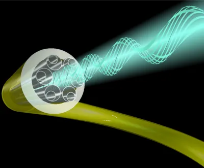
single-mode fibers (SMF)

Source: University of Southampton

It is too early to know if there will be a dominant design, but the end goal is the same: to guide the light along the core, filled with air or a vacuum, in order to get as close as possible to speed-of-light transmission in free space.
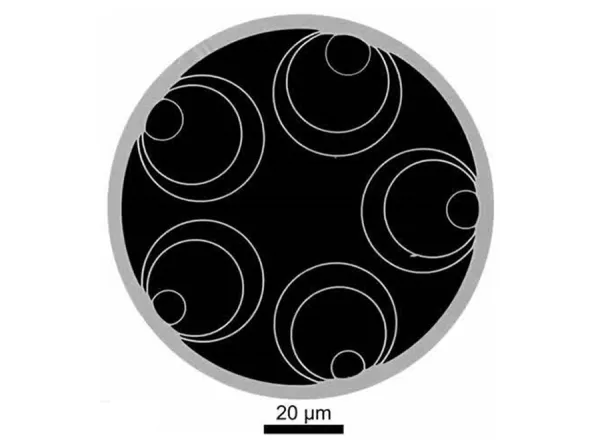
Double nested anti-resonant nodeless fiber (DNANF)


Double nested anti-resonant nodeless fiber (DNANF)
Source: University of Southampton
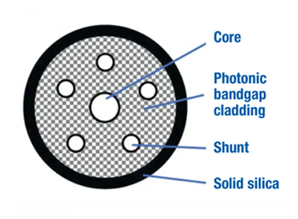
Photonic bandgap guiding (PBG)


Photonic bandgap guiding (PBG)
Source: Lightera

These air-guided structures significantly reduce the interaction between light and fiber material, resulting in several performance advantages.

Key Benefits of HCF

Hollow core fiber offers several significant advantages, including:

  • Lower latency: HCF transmits light at nearly the speed of light in vacuum, resulting in latency of approximately 3.33 µs/km, compared to 4.9 µs/km for SMF
  • Reduced chromatic dispersion (CD): HCF typically exhibits CD values <5 ps/nm/km, while SMF shows ~17 ps/nm/km
  • Equivalent polarization mode dispersion (PMD): HCF can achieve PMD values below 0. 1 ps/√km, compared to 0.1 ps/√km for SMF
  • Reduced nonlinear effects: Due to minimal light-material interaction, HCF exhibits negligible nonlinearities
  • Lower attenuation at specific wavelengths: Recent advancements have achieved attenuation as low as 0.07 dB/km, outperforming typical SMF values of ~0.2 dB/km
  • High damage threshold: The air core allows HCF to handle higher optical powers without thermal damage

Fast Pace of Development

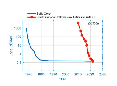
The following figure shows the evolution of solid core fiber versus hollow core fiber in terms of attenuation levels (dB/km). It has progressed significantly in just the last 10 years and now offers lower attenuation per kilometer than standard single mode fiber.

HFC vs SMF Loss Reduction Over Years

Source: University of Southampton

However, HCFs also present certain challenges. Their fabrication is complex and requires advanced techniques, which contributes to higher costs. Some designs may have limited spectral bandwidth, and the fibers themselves can be more mechanically fragile than standard glass fibers.

Qualifying HCF Installations

Deploying hollow core fiber (HCF) introduces a unique set of challenges that differ significantly from conventional SMF installations. Proper qualification requires adapting both tools and procedures to account for the distinct physical and optical properties of HCF.

SMF-to-HCF Adapter Loss

Transitioning from SMF to HCF introduces coupling inefficiencies due to mismatched mode fields and core geometries. Adapter losses can range from 0.2–3 dB, depending on alignment precision and connector quality. These losses must be carefully measured when commissioning a link. The transition from glass-air also generates a high reflection of up to -15 dB when not properly done, this will be a challenge for an optical time domain reflectometer (OTDR), it will generate tailing on the trace and may mask some events close to this first connection. It is important to control this first adapter and ensure reflection as low as possible: better than -50dB.

Bending Radius and Bend Sensitivity

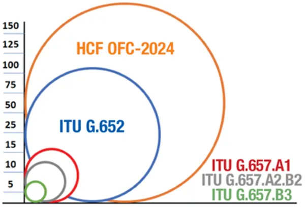
HCFs are 10× more sensitive to bending than SMFs due to their complex micro-structured design and air-core geometry. While SMFs can tolerate bend radius as low as 7.5 mm (especially bend-insensitive variants), HCFs often require minimum bend radius of several centimeters to avoid excessive attenuation or structural damage. This makes HCF less suitable for tight routing environments unless specifically engineered for bend tolerance. Installers must ensure proper routing and strain relief to maintain performance. The following figure shows the different bending radius of different fibers compared with hollow core fiber. 

Minimum bending radius HCF vs. ITU G.657

Minimum bending radius HCF vs. ITU G.657
Source: Broadband library

Rayleigh Backscattering (RBS)

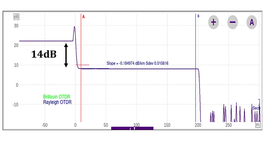
HCF exhibits RBS levels approximately 14 to 20dB lower than SMF. This significantly affects OTDR trace visibility, making it harder to detect events and measure distances with standard OTDR settings.

Variable Backscattering Coefficient

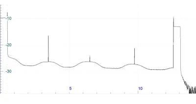
Unlike SMF, where backscattering is relatively uniform, HCF may show non-uniform backscattering along the fiber length due to microstructural variations. This complicates OTDR trace interpretation and requires different test settings than for SMF (K factor).

OTDR trace showing the variation of RBS coefficient and the reflective splices

Standard uni-directional OTDR trace showing the variation of RBS coefficient and the reflective splices

Variable backscatter coefficient also means that bidirectional OTDR test and analysis is the only method suitable for characterizing fiber and splice losses. In addition, the standard bidirectional OTDR analysis algorithms and tools will not be able to manage and produce meaningful results again due to the variable backscatter coefficient.

HCF-to-HCF Splice Loss

Fusion splicing between HCF to HCF segments is more complex and can result in splice losses of 0.1–1.5 dB, depending on fiber alignment and cleanliness.  Compared to splices between SMF to SMF, HCF to HCF splices generate reflectance which exceed the backscattering level (as shown above) which create dead zones. In the field, splices could be 2 to 4 km apart; therefore it is important to have an OTDR with high dynamic range at short pulse to be able to measure each of them without merging of events.

Non-Standard OTDR Traces

HCF produces different OTDR signatures compared to SMF. The lower backscatter (-14 to -20dB) and unique modal behavior result in different traces, reflective splices and infiltration of ambient air components around the splice point. Standard OTDR settings may fail to detect key features, requiring different testing parameters such as pulse width and averaging time.

Trace from a coherent ODTR measuring 14dB difference of RBS from SMF to HCF

Trace from a coherent ODTR measuring 14dB difference of RBS from SMF to HCF

OTDR test wavelength

Currently most HCFs are optimized for operation in the S-band (starting around 1450nm) and above. Hence OTDR testing at 1310nm, as typically done with standard SMF, will not produce relevant or useful results so testing at 1550nm is required. As with SMF testing, using additional wavelengths allows for better fiber and splice loss characterization and bend detection. Therefore, at present HCF will require measurements at 1550nm and 1625nm for field acceptance testing.

Post-Processing Analysis (HCF Loss Profile)

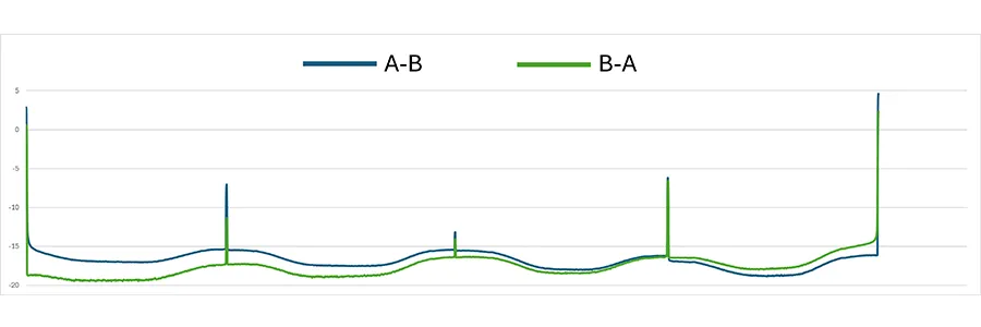
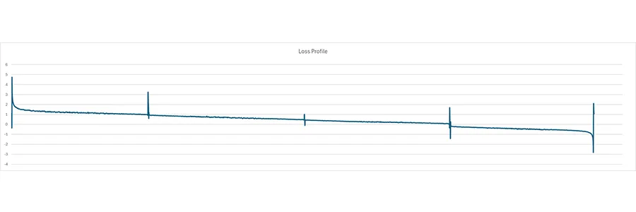
Due to the unique trace characteristics (RBS varying along the fiber), standard OTDR post-processing analysis algorithms do not apply. Custom software or manual interpretation is often needed to assess splice quality, connector loss, and fiber integrity. It is necessary to match each measurement point from each direction, align the two traces and make a bidirectional analysis, (AB-BA)/2, to obtain the actual loss profile. Loss profile trace obtained by bidirectional analysis will then allow measurement of attenuation for each HCF section and the loss of each event on a link. 

OTDR traces acquired from testing HCF in both directions (A-B and B-A)

OTDR traces acquired from testing HCF in both directions (A-B and B-A)

Loss profile trace obtained by performing bidirectional analysis

Loss profile trace obtained by performing bidirectional analysis

To learn more about selecting the right HCF test equipment, OTDR setup, testing procedure, result processing and analysis, download this Hollow Core Fiber Testing application note

As HCF is relatively new and manufacturers are in the early stages of production and field trials it would be prudent to verify additional characteristics. In addition to bidirectional OTDR testing and bidirectional OTDR analysis, some attention should be paid to attenuation profile (AP), chromatic dispersion (CD), and polarization mode dispersion (PMD).

In order to confirm HFC is installed properly, it should be characterized completely (OTDR, AP, CD, PMD) to avoid any compromise in initial or future performance.

Attenuation Profile (AP)

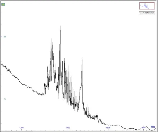
Attenuation profile testing helps identify non-ideal transmission characteristics such as absorption regions (attenuation) caused by water vapor. During manufacturing the presence of gas could generate a degassing process creating absorption at certain wavelengths.

The AP of standard glass fibers is well known and is homogeneous from one manufacturer to another. Unlike HCF, where we are at the early stages of production and deployment, new HCF technologies and manufacturing processes are leading to different profiles.

As a result, post-installation testing of the attenuation profile becomes essential to validate the actual transmission capacity of the link, confirm manufacturer specifications, and ensure compatibility with system requirements. This is especially important in applications where wavelength-specific performance is critical

In field trials, a significant number of manufacturers and end customers have requested this information to assess link quality and verify performance claims before type approving or accepting a link.

Hollow core fiber attenuation profile measurement

Hollow core fiber attenuation profile measurement

Chromatic Dispersion (CD) and Polarization Mode Dispersion (PMD)

HCF are designed to transmit longer distance and higher speed therefore dispersion could have an impact on future upgrade of transmission rate, knowing the real base line is important.  Even though dispersion effects are much lower in HCF versus SMF there is a risk of inconsistency as new HCF manufacturing processes are established, validation of CD and PMD parameters ensures nothing unexpected has occurred after splicing all HCF sections together.

Therefore, in addition to bidirectional OTDR testing, CD and PMD are key for full HCF link characterization and certification. However, OTDR-based dispersion tests are limited by the same 14–20 dB drop in Rayleigh backscatter and dynamic range constraints, making them suitable only for short links.

A more accurate approach uses dedicated optical broadband light sources and dispersion measurement devices, such as the VIAVI OBS-500 optical broadband source and Optical Dispersion Measurement (ODM) module, bypasses these limitations and enables reliable long-distance testing

Techniques such as phase shift for CD and fixed analyzer for PMD offer precise results with greater dynamic range.

To learn more about the Fiber Characterization download our poster here.

Standard OTDR can be used for testing hollow core fibers, solutions such as the VAVI 4100 series C module and 8100 series D module, are well suited to testing hollow core fibers thanks to their dynamic range, dead zone performance, and photodiode sensitivity and recovery capabilities. These modules can be hosted on a range of VIAVI platforms, such as the T-BERD/MTS-4000 V2 and the OneAdvisor 800 Fiber.

To learn more about how to spec OTDR dynamic range for HCF test download this Hollow Core Fiber Testing application note

Bidirectional analysis of the A to B and B to A OTDR test results can be performed immediately, while tech crews are still on-site, using VIAVI Report PRO software. This application supports hollow core fiber analysis.

The OneAdvisor 800 Fiber platform has the added advantage of being able to host the VIAVI Optical Dispersion Measurement (ODM) module, as well as OTDR modules, making it an all-in-one solution for bidirectional OTDR, CD, PMD, and AP testing. In addition, the OneAdvisor 800 can have functionality expanded further with modules for BERT/400G Ethernet testing.

HCF is gaining traction in industries where speed, security, and low latency are critical:

  • AI & High-Performance Computing: Facilitates high-bandwidth, low-latency links for synchronization, AI model training and distributed computing
  • Data Centers: Enables faster, low latency interconnects and longer reach without amplification
  • Quantum Communication: Supports low-noise transmission for quantum key distribution
  • Defense & Secure Communications: Air-guided structure makes HCF resistant to physical tapping
  • Financial Trading: Reduces latency for high-frequency trading environments
  • Smart Cities, Edge Computing and 5G/6G Infrastructure: Enables responsive networks required for autonomous systems and real-time data processing

The Future for Hollow Core Fiber

Hollow core fiber offers transformative potential for optical networks by offering unmatched speed and performance, but its successful deployment hinges on rigorous testing and qualification. From bidirectional OTDR analysis to dispersion testing, understanding the nuances of HCF testing is essential for ensuring performance and reliability. As deployment scales, robust testing methodologies will be essential to ensuring reliability, interoperability, and long-term viability.

To learn more about selecting the right HCF test equipment, OTDR setup, testing procedure, and result processing and analysis, download this Hollow Core Fiber Testing application note

Ressources

  • Posters

    Understanding Fiber Characterization
  • Notes d’application

    Testing Hollow Core Fibers (HCF)
  • Catalogues

    Test, Analysis and Reporting Solutions for Hollow Core Fiber
Société
  • À propos de nous
  • Carrières
  • Relations avec les investisseurs
  • Communiqués de presse
  • Partenaires
  • Responsabilité sociale
Domaines D’expertise
  • Assurance service
  • Avionique
  • Détection 3D
  • Fibre
  • Tests de la 5G
Support
  • Service clientèle
  • Assistance technique
  • Portail de support
  • Réparation et calibrage
  • Téléchargement de logiciels
Comment acheter
  • Demander un devis
  • Contacter un expert
  • Localiser un partenaire
  • État des commandes
viavi logo
  • Facebook
  • Instagram
  • LinkedIn
  • Twitter
  • YouTube
Subscription Center

© 2025 VIAVI Solutions Inc.

  • Préférences de cookies
  • Nous contacter
  • Plan du site
  • Mentions légales
  • Politique de confidentialité
  • Assistance technique
  • Demande RMA
  • Obtenir un devis
  • Nos distributeurs
  • Portail client
  • Nous contacter