What is High-Split Leakage?
Learn how to monitor leakage in high-split networks and see available detection systems.
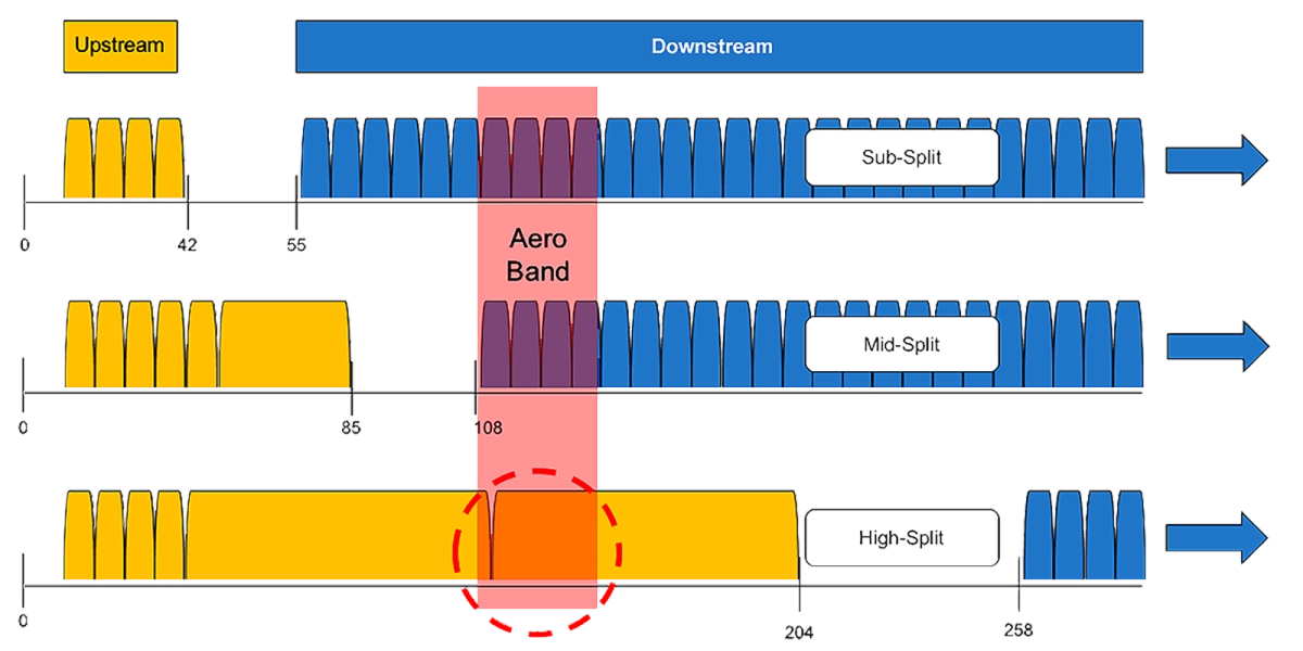
Aeronautical band monitoring is mandated by the FCC in the United States, and solutions have been developed and perfected to monitor signal leakage from cable downstreams at 138MHz. Moving the upstream diplex frequency out to 204MHz results in the aeronautical band residing within the upstream frequency band, breaking many existing downstream signal tagging methodologies. Despite the challenges created, there is no indication that the FCC will relax the aeronautical band mandate so solutions must be found to enable continuation of this monitoring. High-split leakage is therefore the ability to monitor signal leakage from cable networks including the aeronautical band residing in the upstream spectral range.
Beyond just meeting governmental mandates, operators globally recognize how using leakage to keep networks tight drastically reduces upstream ingress issues, and as many leaks are frequency-specific it is not desirable to lose all visibility into leaks below 258MHz. The same is true for FM ingress – which will be more difficult to localize as an upstream issue in high-split nodes without having signal leakage capabilities to identify shielding weaknesses impacting the FM band.
The term “High Split” is commonly used to describe extending the upstream frequency range from 42 or 65MHz up to 204MHz in cable systems. High-split architectures are one option for increasing upstream bandwidth under consideration for many cable operators. Extending the cable upstream from 42MHz to 204MHz provides more than a 500% increase in usable spectrum, but does not come without challenges. One of these challenges is shifting the aeronautical band from the downstream to the upstream, effectively breaking existing leakage monitoring methods.
Many options have been discussed for addressing the high-split leakage challenge:
- Monitor the lowest downstream frequencies as a proxy for the aeronautical band. This option is a non-starter as it does not meet the specific FCC mandate to records emissions in the aeronautical band.
- Downstream signal tag transmission via either notch filters and/or upconversion. Neither of these options are practical due to upstream spectrum loss required to implement them and complexities that they introduce into other network elements.
- Upstream tag signal generated by each cable modem. This solution makes intuitive sense – simply command each cable modem (CM) to replicate the signal leakage tag or CW at a specific time and/or frequency. These tags could then be detected by existing signal leakage equipment with no changes needed. Unfortunately, this is not what CM’s are designed to do and significant changes would be required on both the CM and CCAP to accommodate this and properly manage levels, timing, etc.
- Use CM test bursts already present in existing specifications. This is the path generally favored by industry consortiums, service providers, and test vendors. DOCSIS 3.1 already specifies OFDMA Upstream Data Profile (OUDP) test burst operation, and these test bursts have characteristics that lend themselves well to detection by advanced leakage meters.
What is OUDP Leakage Detection
As mentioned above, OUDP test bursts are designed into the DOCSIS 3.1 specifications covering both CCAP and CPE operation, and are generally used to determine the maximum modulation that CPE can support at a given time for a given frequency range. Think of these test bursts as a “what if” analysis – a way to see how the CM would perform if operating at a higher Interval usage Code (IUC). Since live data packets are never transmitted through OUDP test bursts, there is no danger to service degradation when testing performance of higher IUC’s. These OUDP test bursts can also serve another very valuable purpose, they can act as leakage tags transmitted in the aeronautical band for high-split nodes.
There are multiple different OUDP pilot patterns documented in the DOCSIS 3.1 Specification, but early testing has found those with the most dense concentration of pilots provide the most robust detection opportunities. While the most dense existing pilot patterns appear to be adequate to enable leakage detection based on early investigations, it is possible that even higher density pilots could be added to the DOCSIS 3.1 specifications in the future to improve overall high-split leakage robustness and sensitivity.

High-Split Leakage Detection Systems
Fortunately there are leakage solutions today with hardware capable of OUDP detection like the VIAVI Seeker X platform. Cable operators can purchase and use the systems today to tighten up their existing sub/mid-split networks, including the FM ingress band which will be much more difficult to work with when it’s part of the upstream post-high-split migration. When the time comes to migrate the upstream to 204MHz, simply remotely deploy a license key and new frequency plan to the Seeker X via the Mobile Tech app to add OUDP to existing leakage detection capabilities.

Other characteristics that make Seeker X ideally suited for high-split leakage:
- Software-defined radio architecture adaptable to different tags such as OUDP
- Powerful FPGA to concurrently handle OUDP detection and existing downstream capabilities
- Full frequency agility 130-1220MHz
- Wideband vehicle and field antennas enabling full utilization of meter frequency agility
- Connected solution – remote admin, display, control via mobile app
Start detecting signal leakage with VIAVI today!
Are you ready to take the next step with one of our signal leakage products or solutions? Complete one of the following forms to continue: