Test and the Evolving HFC
The race is on for service providers to deliver Gigabit speeds and service reliability at levels unheard of just a few years ago. Hybrid fiber coaxial (HFC) networks are rapidly evolving to meet these demands.
New technologies such as DOCSIS 3.1, and distributed access architectures (DAA) like Remote PHY (also known as R-PHY) are extending the life of the HFC plant by leveraging much of the existing infrastructure to deliver Gigabit speeds. This is being done while also pushing out or eliminating the need to pull fiber to each subscriber location. Even more advanced technologies, such as Full-Duplex DOCSIS, are on the horizon with the promise of enabling symmetrical gigabit offerings. This will allow new service offerings such as wide-scale 5G mobile backhaul – creating the possibility of new revenue streams for service providers.
These evolutions are exiting, but also create challenges for the people that must monitor and maintain the HFC plant. The need for critical test capabilities that operators have relied on for years is stronger than ever, but the processes and tools used to provide those capabilities must evolve with the changing HFC. This must all happen while dealing with important day-to-day challenges such as customer churn resulting from poor service quality and holding the line on OpEx since the average revenue per user is stagnate. All of this creates the perfect storm for HFC maintenance processes and tools.
This multi-part series has been designed to help navigate service providers through this evolving landscape and will investigate several aspects of test in the evolving HFC.
HFC Evolution – Remote PHY + DOCSIS 3.1 Lead the Way
Several changes are happening to keep up with subscriber demand. There are an exponential number of node splits happening to reduce the size of the downstream service groups to the level required for delivering gigabit services. In some cases, doubling or tripling the number of nodes over just a two or three-year period. While this can increase speeds, it also creates new problems in operator hubs. The exponential number of nodes splits means more rack space, power and cooling capacity are required.
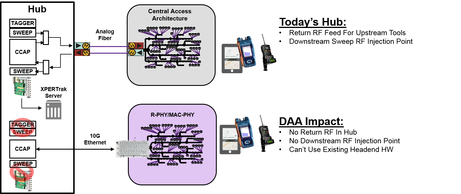
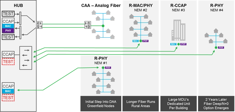
To combat this issue, DAA technologies like remote PHY are being deployed that virtualize and migrate certain aspects of the network and reduce the need for rack space, power, and cooling in these facilities. Hubs are evolving from housing row after row of specialized equipment and RF splitting/combining networks, into potentially nothing more than a small collection of optical switches. This new technology inflection has created a proliferation of NEMs in the market giving operators more choices, but also creating confusion and complexity around testing. In addition, this new virtualization eliminates the RF feed in the hub making testing more challenging.
DOCSIS 3.1 enables up to 50 percent more capacity over the same spectrum helping to keep CapEx and OpEx down while greatly increasing throughput. But DOCSIS 3.1 is much more complex than its predecessor, mainly due to orthogonal frequency domain multiplexing (OFDM) and low-density parity check (LDPC). In addition to adding multiple subcarriers, DOCSIS 3.1 enables optional frequency extensions to increase throughput. Field meters will need to be upgraded to 3.1-compatible versions if service level testing is to be performed, and nearly anything with a diplexer will need addressed to handle the frequency split changes. Also, field technicians will need to learn how to interpret the test results. Are codeword errors okay now, and to what level?
Coming fast on the heels of DOCSIS 3.1 rollouts is Full-Duplex DOCSIS (FDX) promising multi-gigabit symmetrical services using the existing last-mile HFC infrastructure. FDX will generally require N+0 to operate, and while elimination of amplifiers will simplify some aspects of plant maintenance, many of today’s problems will still remain. It is also expected that FDX will require new chipsets for service provision equipment including field meters. Non-modular instruments will need to be scrapped and replaced, but a newer generation of testers with modular meters will only need to swap in new FDX-enabled modules.
The path operators take to evolve the HFC will be gradual and inconsistent throughout the plant. Advanced technologies will need to be deployed in certain parts of the plant sooner than others to keep up with demand. Lesser used areas might keep legacy technology longer to keep costs down. This creates a challenge for operators trying to maintain standardized testing procedures. Ways to alleviate these challenges will be discussed in the other documents within this series.
The short answer is YES! Customers will still leave if service is poor. Connectors still corrode, cars still hit poles, and subscribers still mess with their in-home wiring. Also, in the modern HFC, every bit of capacity is important. Plants must be clean to pass more packets and reach the higher modulation orders for DOCSIS 3.1. As mentioned before, DOCSIS 3.1 can add as much as 50 percent more capacity using the existing plant, but that plant must be clean for this to happen. Testing is the only way to ensure a clean plant for both legacy and remote PHY nodes.
The same aspects of the HFC that need to be tested today will still need to be tested tomorrow:
- Plant turn-up and characterization
- Ensure quality of new service installations
- Identify customers at risk of churn and the specific plant issues creating this risk
- Field troubleshooting to find and fix issues
- Identify areas where plant maintenance will have a positive ROI and efficiently support the hardening process
- Detect areas of sub-optimal plant utilization, identify root cause(s) and support the remediation process
Again, the answer is YES! Testing solutions are evolving to meet the needs of the evolving HFC. Physical testing units are becoming modular to keep up with the changing plant without the need to totally replace the testing units. In many cases, once a unit is upgraded, it can still test legacy technologies reducing the need to keep and carry older testing units. Many of the complex tests needed for new technologies are embedded in the units to provide easy to read results, and in some cases, have pass/fail results to streamline testing for technicians.
DOCSIS 3.1 gear is already available and software-based solutions are available to test and monitor virtualized portions of the HFC such as DAA technologies. FDX gear will be ready when needed, ideally as module upgrades to existing gear. Smart software platforms are available to orchestrate virtual gear and meters to save time and manpower.
The burning question of those in charge of plant maintenance is not IF testing is still needed in the evolving HFC, but HOW that testing will take place. The very changes that will allow Gigabit services to millions of subscribers like Remote PHY will necessitate changes in processes and the tools used to keep plants running a maximum efficiency.
Virtualization is certain to play a pivotal role using deployed network elements as probes that replace dedicated hardware in some cases. Software solutions will process massive amounts of data into actionable results in this virtual environment. This will place the focus on specific plant issues causing subscriber churn and minimize the field time required to locate them.
Filed instruments will evolve to be more adaptable and will interact with both physical and virtual test systems to further reduce the mean time to repair issues. Perhaps the key to it all is the ability of test systems to keep up with the changes while insulating the technicians from the massive proliferation in plant changes and the underlying complexity that will result. The next document in this series will talk about the techniques and tools needed to test return sweep in the new and evolving HFC.
Return Sweep
In the above section we spoke of how the hybrid fiber coaxial (HFC) plant is evolving and becoming more virtualized. This is great for service providers looking to increase capacity while keeping CapEx and OpEx in check but creates challenges for critical plant maintenance practices like sweep. For the downstream, sweepless sweep is generally regarded as an acceptable solution for most use cases, but acceptable solutions for the upstream are not as straightforward. For that reason, this document will focus on the challenges these new technologies create for return sweep and will present options to solve these issues.
Return sweep remains a critical tool for many of the most common use cases from within legacy plants and will continue to apply in the evolving HFC network. The same realities of the legacy HFC plant still apply as fiber gets pushed deeper and DOCSIS 3.1 rolls out. For example, customers still leave if service is poor. Connectors still corrode, cars still hit poles and subscribers still mess with in-home wiring. In addition, return sweep is critical to ensure the clean plant needed for DOCSIS 3.1 to reach higher modulation orders and deliver maximum capacity.
Return sweep is used in several areas to ensure the HFC is best optimized for performance. It can and should be used to pre-qualify spectrum prior to turning-up new services. This eliminates a lot of problems before a service goes live, and issues are much easier to fix at this stage than once a service is live. Pre-qualifying spectrum is also critical for DOCSIS 3.1 as the upstream spectrum boundaries can reach 204 MHz, further complicating any potential issues.
Amplifier alignment is another great use for return sweep. Technicians use return sweep to set up new amplifiers and adjust for plant architecture changes. Return sweep is the preferred method of maximizing plant margin and robustness by maintaining unity gain. It is also great for proactive plant maintenance where technicians cleanup and proactively optimize the plant before customers are impacted by service disruptions.
When something does go wrong, return sweep plays an important role in real-time field troubleshooting including outages when critical DOCSIS services are down. Return sweep can quickly and accurately validate a failing segment and pinpoint the exact location of a fault. It can also be used to validate the findings of the Proactive Network Maintenance (PNM) tool before conducting a repair effort that may use significant resources such as digging up a road to fix a bad span.
There are three main challenges for return sweep as the HFC continues to evolve. Fiber deep programs enabled by Remote PHY will exponentially increase the number of nodes to achieve smaller downstream service group sizes. Multiple operators are projecting a 300-500 percent increase in the number of nodes within the next five years. At this level, it becomes prohibitive to proactively sweep so many nodes.
Distributed access architectures such as Remote PHY and Remote CCAP create another challenge by removing the RF test points from hubs, prohibiting the use of hub-mounted RF sweep gear. Since parts of the hub become virtualized in this new environment, it will be vital to have virtual methods to maintain return sweep capabilities.
Fiber Deep ≠ N+0: A common question is, “With DAA and fiber deep eliminating amplifiers from the HFC, why is sweep still needed?” The vast majority of fiber deep plans today are reducing cascade depths from >5+ amps deep to 1-3 amps deep with only isolated N+0 deployments. Selective migration to N+0 is a long-term goal for some MSOs that will enable Full-Duplex DOCSIS (FDX) when available later this decade or early in the next. Until that time, the business case is not there to justify this leap in most cases.
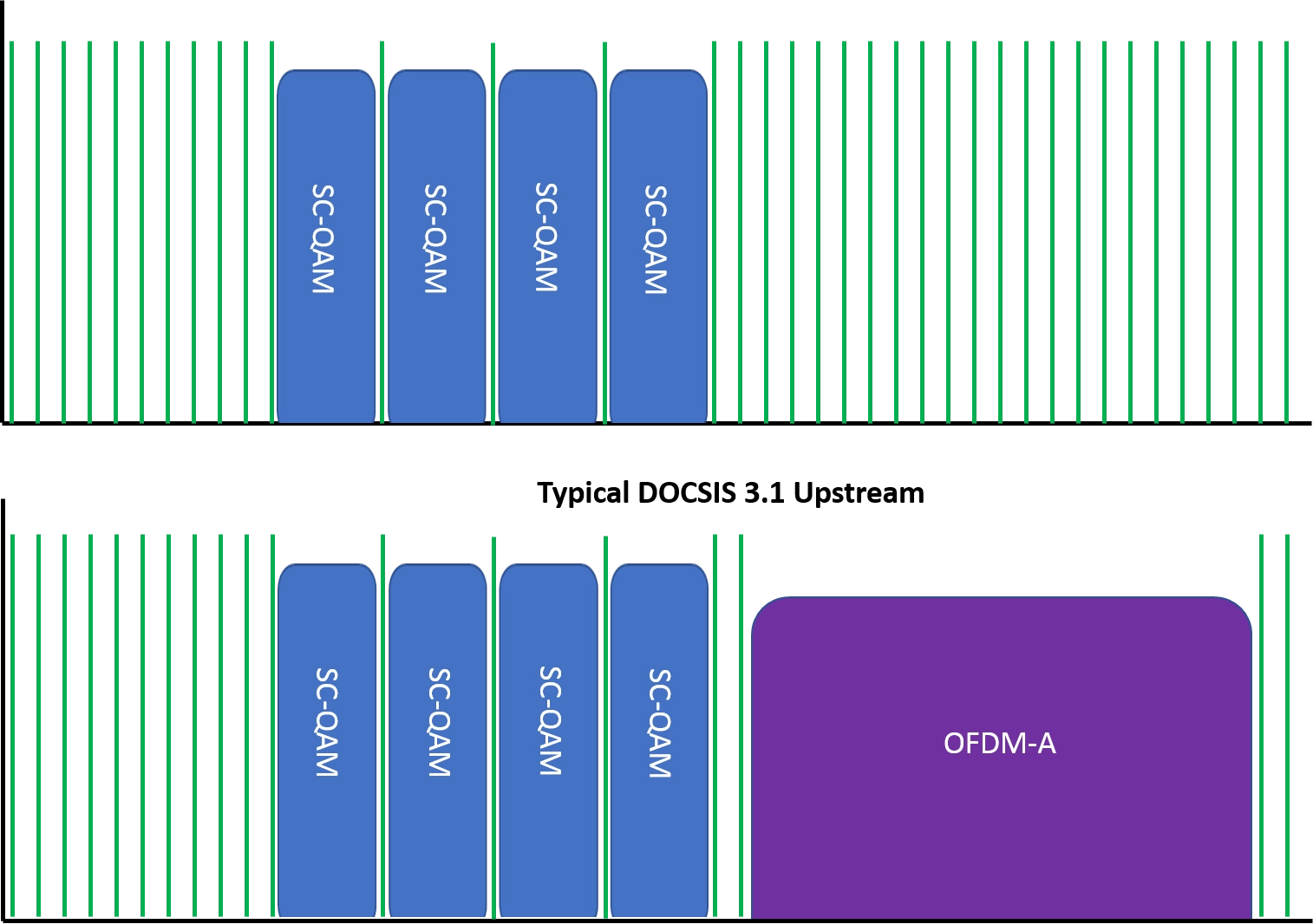
Best practice for return sweep has been to inject sweep pulses in vacant spectrum at the top and bottom of the upstream spectral range and between the QAM carriers to minimize the chances of interfering with services. For DOCSIS 3.1, the wider boundaries of orthogonal frequency division multiple access (OFDM-A) make sweep pulse injection between carriers impossible from coverage standpoint since the carriers are many times wider than single carrier QAM’s (SC-QAM).
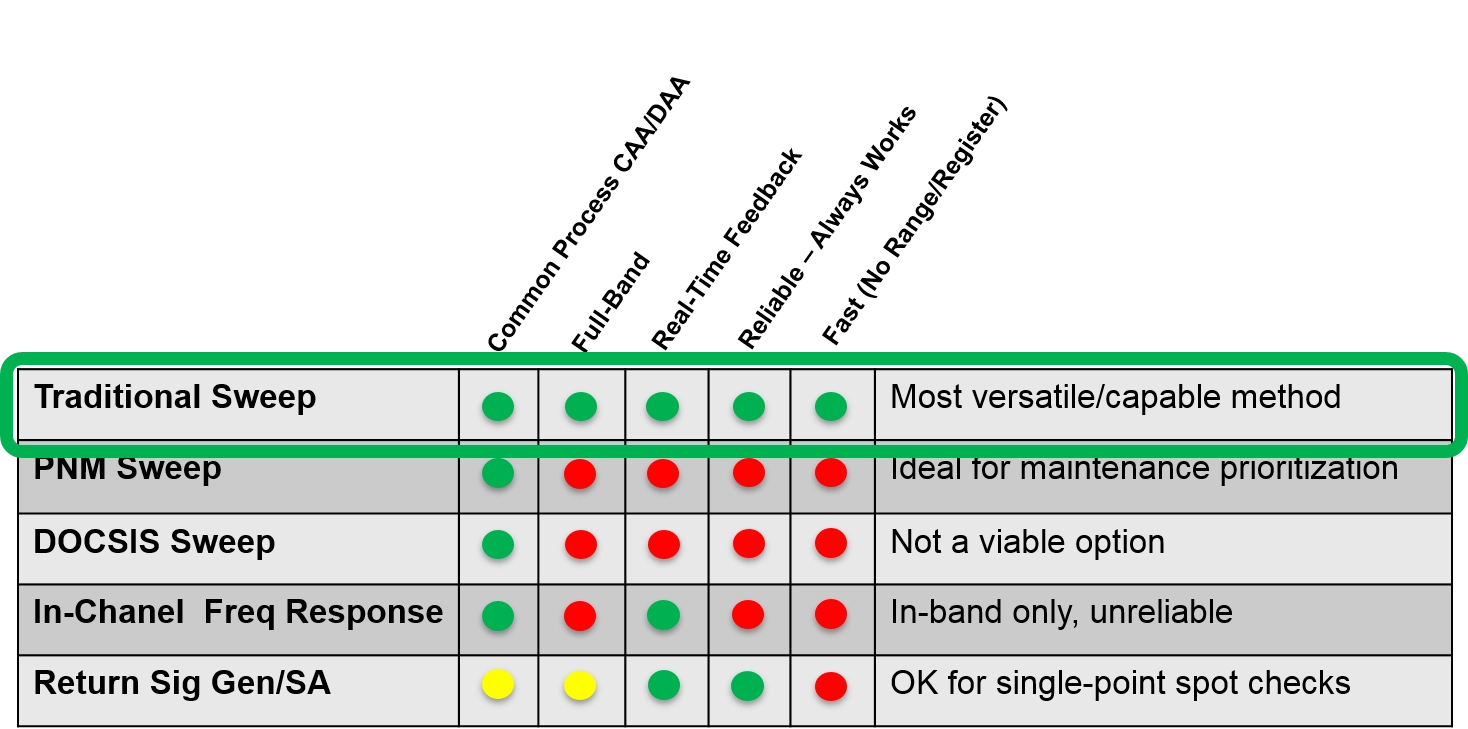
MSOs globally have identified return sweep as a critical test function and have reached out to test vendors for a path forward in the evolving HFC. Ideally, any solution should be able to conduct return sweep tests on legacy systems as well as newer virtualized technologies like Remote PHY as they are deployed in the HFC plant. There are five main options for return sweep in this new environment. Let’s look at each one and discuss the strengths and weaknesses of each approach.
Proactive network maintenance (PNM) has become more mainstream in the past several years and provides a remote inspection of the network. In some ways, it has taken the place of physical proactive maintenance where technicians go through the plant proactively looking for issues before subscribers are affected.
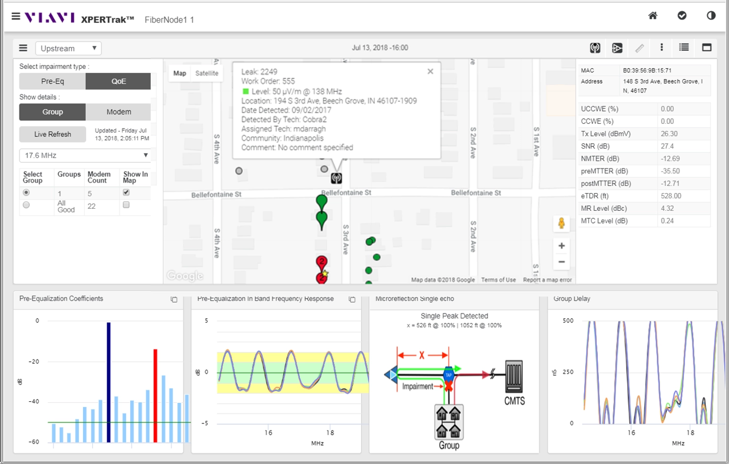
PNM uses upstream pre-equalization to remotely detect and localize impedance mismatches. Existing PNM systems simplify the identification of plant sections needing maintenance by capturing the pre-equalization responses, grouping modems that have statistically similar responses, and correlating grouped modems to a plant map to find the least common denominator plant component. This makes PNM ideal for maintenance prioritization.
DOCSIS 3.1 adds its own capabilities to PNM sweep by adding upstream symbol capture capabilities. In this case, the cable modem termination system (CMTS) captures a specific symbol transmitted by the CPE and the PNM server solves for the difference between the known transmitted signal and the “as-received” condition to determine the frequency response of the transmission path. In other words, it solves for the difference between what was expected on the receive end and what was actually received.
The upstream pre-equalization of PNM, and the auto-detection of downstream impairments via data from full-band capture CPE, make PNM an excellent tool to identify plant sections with significant linear impairments that need to be prioritized for sweep. It can also show which sections of the plant would not yield a positive ROI by using proactive sweep. The downsides to PNM for return sweep are that it can only cover occupied spectrum and doesn’t work if DOCSIS services are down. PNM also takes 30-45 seconds to get results each time a technician makes an adjustment, which can be too slow for conducting real-time troubleshooting in the field.
DOCSIS sweep works much like downstream sweepless sweep in that it uses carriers for the sweep, but in this case uses the upstream carriers. DOCSIS sweep measures the frequency response at each carrier, normalizes the data and then saves this as a reference. It does the same at the next test point and then compares the two references. The difference between the two is the frequency response for the segment.
DOCSIS sweep is great for final verification of maintenance actions using the customer CPE, but is too slow, unreliable and incomplete in spectral coverage for real-time field use. It is also challenged by the rapidly changing power levels in DOCSIS 3.1 and the variable bonding counts.
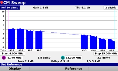
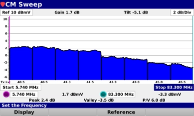
This is the least helpful of the five options as it is unreliable and only shows the In-band frequencies. In this option, the technician simply views the ICFR as measured on the test instrument as shown at right. This provides a raw, non-normalized view of the data and the technician uses it to determine if the frequency is flat or not.
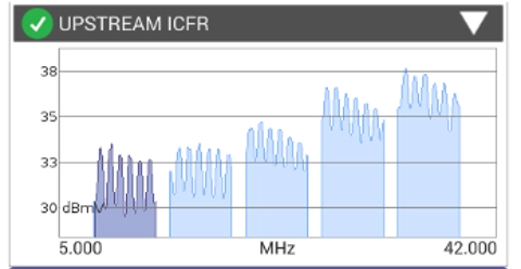
For this option, the technician injects continuous waveforms (CW’s) in vacant spectrum from field with a meter, shooting back signals at a specific time. The signal is then measured at the headend with a spectrum analyzer. This option is still a standard maintenance practice for ad-hoc level checking but is impractical as a standard process across the HFC plant since it is slow, highly manual, and is difficult to execute in a DAA plant with no RF access is hub.
Traditional sweep is still the best alternative in nearly all use cases. It’s reliable and fast, providing real-time feedback, and offers full-band coverage to cover both occupied and vacant spectrum. The biggest challenge to traditional sweep is the virtualization of network functions that remove the RF feed at the hub as with Remote PHY. This creates a challenge for sweeping distributed access architectures. Is also creates a challenge for sweeping with wider OFDM-A carriers of DOCSIS 3.1.
VIAVI has developed a solution enabling operators to sweep legacy and DAA/DOCSIS 3.1 networks with no change to deployed field meters or established technician workflows. The sweep receiver and downstream telemetry functions are migrated to the Remote PHY unit (RPU) with orchestration and communications being handled by the VIAVI XPERTrak R-PHY/CCAP Interface (RCI) software. This standards-based approach is supported by top DAA vendors and requires no additional specialized hardware. VIAVI sweep systems also enable sweeping through OFDM-A carriers enabling full spectrum visibility with no perceivable service impact.
Sweeping Through OFDM-A Carriers: Extensive research has been completed assessing potential service impact of sweeping through OFDM-A carriers. While there can be negligible packet loss under a small minority of network loading and sweep configuration conditions, under no circumstances was it sufficient to cause VoIP MOS scores to drop below 4.0. Upstream sweep pulses are only present while a tech is testing and sweeping through carriers is generally performed while repairing critical plant faults. This is considerably less intrusive than most other common plant troubleshooting practices.
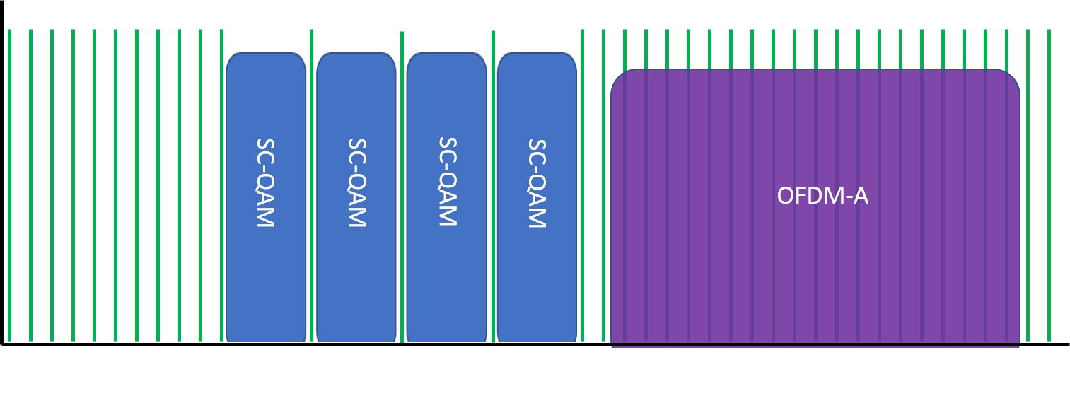
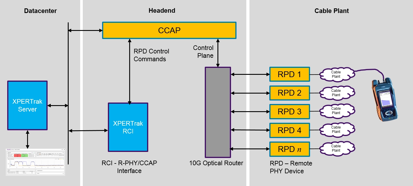
The HFC is evolving rapidly to meet ever-increasing market speed and quality demands, and this evolution creates challenges for critical test capabilities like return sweep. Alternative methods like PNM and DOCSIS-based capabilities have been developed to address specific use cases, but traditional sweep is still the superior alternative for most use cases.
Operators globally have communicated their strong desire to maintain this foundational capability through the current and upcoming HFC transitions. Test vendors have listened and have a solution available that works in both legacy and advanced nodes using existing procedures and field instruments. By ensuring that network evolution plans include provisions for critical plant maintenance capabilities like return sweep, operators can greatly increase their chances for a smooth transition to the HFC of the future.
Test and the Evolving HFC: Monitoring
The hybrid fiber coaxial (HFC) plant is rapidly evolving to address market demands and this transformation is driving changes in how the HFC is maintained. DOCSIS 3.1 and distributed access architectures (DAA) like Remote PHY are greatly extending the life of the HFC plant by leveraging much of the existing infrastructure to deliver Gigabit speeds while pushing out or eliminating the need to pull fiber to each subscriber’s location.
But these advancements are creating challenges for the people that must monitor and maintain the HFC plant. In this installment of the Test and the Evolving HFC series, we focus on the impact this evolution has on plant and subscriber monitoring, the challenges it creates, and alternatives that are available to alleviate these challenges.
Monitoring the HFC remains critical for many of the most common use cases from within legacy plants and will continue to apply in the evolving HFC network. The same realities of the legacy HFC plant still apply as fiber gets pushed deeper via Remote PHY and DOCSIS 3.1 rolls out. For example, customers still leave if service is poor. Connectors still corrode, cars still hit poles and subscribers still mess with in-home wiring.
In fact, monitoring has become even more critical in recent years as subscribers are more sensitive to service quality than ever before. Monitoring is used to alert technicians to a subscriber or plant issue, often times allowing the technician to make the fix before the subscriber notices a degradation in service quality. Monitoring also plays an important role within the HFC plant itself as it ensures maximum throughput is achieved, eliminating or at least deferring the need to split nodes or buy more CCAP ports.
Monitoring serves several important roles throughout the HFC plant. It can identify customers that are most at risk of churn due to poor quality of experience (QoE) and identify plant issues that impact or are about to impact subscriber performance.
Overall plant performance is another area where monitoring excels. It can gauge the throughput of the plant as a whole and proactively pinpoint areas that could be improved. If a problem does occur, monitoring can detect the outage or other major event to speed up the mean time to repair (MTTR). Some monitoring systems also support the field find and fix process by remotely localizing the root cause issues to improve dispatch accuracy, providing live analyzer views to meters and other mobile devices, and giving real-time updates to technicians in the field to keep them informed.
Monitoring plays a financial role as well. It can analyze the trends in plant performance to identify and prioritize areas where repair actions will have the greatest return on investment. CapEx can be optimized by keeping the plant clean so that higher modulation orders can be reached with DOCSIS 3.1 – providing more capacity with the existing plant and therefore deferring the need for node splits.
Fiber Deep
Several changes are happening to keep up with subscriber demand. While the changes are needed, they do create interesting challenges for monitoring. Fiber deep programs are required to enable the downstream service group reductions needed to deliver Gigabit services. These reductions are creating an exponential number of node splits, and in some cases, doubling or tripling the number of nodes over just a two or three-year period. While this can increase speeds, it also creates new problems in operator hubs. The exponential number of nodes splits means more rack space, power and cooling capacity are required. It also means that the number of nodes that must be monitored is increasing exponentially.
Challenges aside, fiber deep programs do present a unique opportunity. They allow for shallower cascades that reduce the potential of issues with active amplifiers. They also shrink the number of subscribers and plant-miles per node, thereby reducing the opportunities for ingress to get into the plant.
Fiber Deep ≠ N+0: The vast majority of fiber deep plans today are reducing cascade depths from >5+ amps deep to 1-3 amps deep with only isolated N+0 deployments. Selective migration to N+0 is a long-term goal for some MSOs to enable full-duplex DOCSIS (FDX) when available later this decade or early in the next. Until that time, the business case is not there today to justify this leap in most cases.
Remote PHY
Distributed access architectures such as Remote PHY and Remote CCAP are being deployed that virtualize and migrate certain aspects of the network and address the rack space, power and cooling issues created by massive node split rates. Hubs are evolving from housing row after row of specialized equipment and RF splitting/ combining networks, into potentially nothing more than a collection of optical switches and routers.
This is great news as less rack space, power, and cooling are needed in the hub, but challenges are created for monitoring and maintenance. DAA removes the RF feed from the hub, disallowing the use of dedicated test and monitoring gear in these locations. This change has a direct impact on actions such as return path monitoring, sweep and transmitting leakage tagger signals.

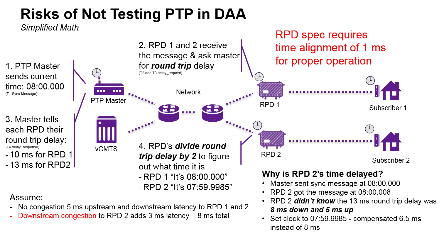
Remote PHY specifically also has the potential of introducing timing issues between the MAC and PHY layers as it separates these layers. The MAC sublayer in Layer 2 functions as a controller that defines how and when modems on a network transmit over shared spectrum without impeding each other, sort of like a traffic cop. Now, with the MAC-PHY separation that occurs with Remote PHY – often by long distances and several network hops — synchronization can become a real issue, creating the potential for service degradation and packet loss. Troubleshooting is difficult for technicians that don’t have the right knowledge and tools to recognize this type of issue.
This new DAA technology inflection has also created a proliferation of NEMs in the market giving operators more choices, but also creating confusion and complexity around monitoring. Many NEMs offer point-solution monitoring tools that work well with their gear but only partially support other vendors gear. Imagine trying to manage multiple monitoring systems from an OSS standpoint, or for the technicians in the field trying to determine which system to use for each node that they work on each day.
DOCSIS 3.1
DOCSIS 3.1 enables more capacity over the same spectrum helping to keep CapEx and OpEx down while greatly increasing throughput as mentioned before. But DOCSIS 3.1 is much more complex than its predecessor, mainly due to orthogonal frequency domain multiplexing (OFDM) and low-density parity check (LDPC). These changes increase the robustness of the plant against impairments but also require new methods of monitoring and troubleshooting.
One of the key issues for DOCSIS 3.1 are the wider orthogonal frequency division multiple access (OFDM-A) carriers that make upstream ingress detection more difficult. This is mainly due to the fact that monitoring guard bands between carriers is impossible from coverage standpoint since the carriers are ten or more times wider than single carrier QAM’s (SC-QAM).
The profiles and multiple subcarriers of DOCSIS 3.1 also create a monitoring challenge with regards to data. The proliferation of profiles and subcarriers means that there is now a seemingly unlimited amount of data to be captured and analyzed. DOCSIS 3.1 also introduces new metrics and changes conclusions that can be drawn from existing metrics such as uncorrectable codeword errors. Monitoring systems will need a way to properly capture this information, and technicians will need to accurately interpret that data.
Continuous Change
The final challenge has nothing to do with a specific technology, but rather how to manage and monitor all of the new technologies and legacy systems as the HFC plant goes through continuous change. The path operators take to evolve the HFC will be gradual and inconsistent throughout the plant. Advanced technologies will need to be deployed in certain nodes or regions sooner than others to keep up with demand. Lesser used areas might keep legacy technology longer to keep costs down vs high-growth areas getting Remote PHY first.
This creates a plant that will be a highly heterogeneous mix of architectures with service provision gear from multiple vendors for at least the next 5-10 years. Operators will face the challenge of trying to keep to a certain level of standards for network performance and monitoring procedures while dealing with this new chaotic environment. Operators will need a way to homogenize results into one common approach as the HFC plant continues to change.
Virtualization of certain aspects of the hub for DAA obviously has its challenges but also creates advantages moving forward. The Remote PHY device can now assume several roles including monitoring the upstream RF, supporting the field find and fix for technicians, and enabling return sweep including real-time field meter interaction. It also provides the RF tagging needed for leakage monitoring and troubleshooting systems.
But virtualization of traditionally hardware-based functions to service provision equipment often presents challenges of its own. For example, as plants virtualize, current CMTS and CCAP units are left to handle spectrum analysis functions. These units are not good as purpose-built spectrum analysis tools because they are slow and don’t provide enough needed information as can be seen in the graph below.
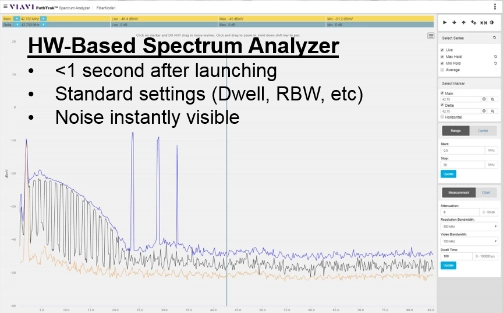
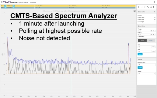
Luckily, some DAA units have recently been developed to conquer this problem and now have greatly improved spectral analysis versus today’s CMTS and CCAP units. Hardware-based return monitoring gear is still best if applicable, but their virtualized distributed counterparts are generally a significant improvement over previous centralized CCAP-based versions.
Customer premise equipment (CPE) can now be used as virtual network probes to increase visibility across the plant without deploying incremental gear. This will help with upstream pre-equalization, downstream Full-Band capture and standard DOCSIS MIBs. Virtualization also allows the CPE to be used as test agents by leveraging excess processing capacity when the CPE is not fully utilized. This is great news as it will allow performance monitoring of the subscriber premise to see problems before they affect the subscriber – keeping customers happy and potentially reducing the amount of truck rolls while minimizing the need for excessive polling.
DOCSIS 3.1 also adds its own enhanced, standards-based monitoring capabilities that are embedded into the technology. The capabilities add features such as upstream and downstream histograms, so operators can quickly see performance issues. It also adds enhanced upstream impulse noise statistics and allows for the testing of the modulation error ratio (MER) per subcarrier.6 Test and the Evolving HFC: Monitoring
All of the increased visibility provided by the CPE and the enhanced proactive network maintenance (PNM) features of DOCSIS 3.1 do have a potential downside – data overload. Millions of CPEs are now capable of delivering measurement data and DOCSIS 3.1 provides multiple metrics on thousands of discrete OFDM/OFDM-A subcarriers. In addition, many more problems that were previously invisible will now be visible. Operators will need intelligent algorithms to selectively collect relevant data and process it into useful information and determine which problems will have a good ROI and which should be deferred for future action.
Data integration and correlation will be important to provide a consolidated view of the entire HFC, and most importantly, the health of subscriber QoE. Current PNM systems are great at detecting issues throughout the plant, but many of the issues don’t currently have (and may never have) an impact on subscriber performance. This leads to many more truck rolls – and expense – without a measurable increase in subscriber QoE. New systems will make the link between plant issues and customer QoE to provide the best ROI.
While this correlation will be vital, it will not be enough as the HFC becomes more complex. As more data pours into monitoring systems for manual analysis, manually interpreting the data becomes impractical. The correlation between plant issues and customer QoE must become automated and more intelligent to deal with the problem. The true value lies in effectively mining the sea of data into actionable information in near real-time.
For example, leakage data could be overlaid with PNM and QoE data on a single plant map. This could greatly simplify the localization of issues before a truck is rolled and show which issues will have the greatest impact on customer QoE. Combining the upstream and downstream monitoring would also assist MSOs in quickly seeing the big picture.

One of the most important trends will be the consolidation of systems for monitoring. The ideal solution will be a single, vendor-neutral system that incorporates inputs from both legacy and virtualized sources including Remote PHY devices and turns that data into actionable insights. It should also greatly simplify life for technicians that must maintain a wide mix of nodes, different architectures and solutions from different NEMs.
This simplification should be possible by providing apples-to-apples comparisons of information regardless of the type of architecture or NEM solution in use. Most of all, a solution should be able to handle all common use cases including ingress remediation, sweep and leakage tagging while interacting with in real-time with field testing units.
The primary drivers for monitoring the HFC have not changed as the plant evolves, but how we monitor is changing rapidly. Plant architecture changes are necessitating the acceleration of virtualization trends. Virtualization is not the magic bullet for all cases as hardware-based solutions are still best for detecting and resolving the “85 percent problem” of upstream ingress and noise. But some of the latest Remote PHY units are adequate substitutes and should get better in the future.
Quality of Experience matters more than ever, and operators should make sure that monitoring solutions maximize customer QoE while also minimizing OpEx and customer churn issues. This can only happen by creating a link between plant issues and customer QoE to provide the best ROI. More data provided by advanced technologies is better but must be intelligently translated into useful information that technicians can act upon in real-time to economically move the needle on customer experience.
Finally, MSOs must have a plan in place to manage the multi-year transition to newer technologies and the resulting heterogeneous plant mix. Success at this will create a standardization of processes – no matter the vendor – and simplify life for technicians.
Field Maintenance
While many of the changes referenced above will increase overall robustness of the plant, they also create challenges for the people who must repair and maintain the plant. There will always be a need for technicians to tighten loose connectors and replace damaged spans, and they will continue to need tools to do their job efficiently and effectively. But the tools and techniques used to conduct field maintenance will change as technologies continue to advance. In this installment of the Test and the Evolving HFC series, we look at these challenges and how the tools and techniques will change.
As mentioned in the previous application notes in this series, the same realities of legacy HFC plant still apply as fiber gets pushed deeper via Remote PHY and DOCSIS 3.1 rolls out. Customers still leave if service quality is poor. Connectors still corrode, cars hit poles and customers still mess with in-home wiring. OpEx is still a scarce resource for operators who must do more with less. There is also a CapEx driver for effective plant maintenance practices in the evolving HFC. If a plant is properly maintained, it can pass more packets through the same frequency range, therefore eliminating or at least delaying the need for expensive node splits.
Even with the increased robustness offered by DOCSIS 3.1 and shrinking cascades via fiber deep, there will always be plant issues that will require truck rolls. While operators are aware of this reality, they also know that fierce competition demands that issues get addressed quickly and within the constraints of their shrinking OpEx budgets. Even as the HFC rapidly evolves, the typical drivers for field maintenance use cases listed below don’t change significantly.
Ingress remediation is still the largest consumer of field maintenance resources, with technicians spending nearly 85 percent of their time addressing upstream ingress. Troubleshooting and repair of ingress are also important as upstream ingress from a single home can take down service for an entire node until it is found and fixed.
Field maintenance is critical for accurately turning up new services as well. The plant must be prepared and qualified prior to turning up new services. This becomes extremely important as DOCSIS 3.1 adds options for downstream expansions to 1.2 GHz and upstream spectrum up to 204 MHz. For Remote PHY deployments, field maintenance can validate new 10G optical Ethernet links and Remote PHY units to ensure everything is working properly.
The HFC plant is in a constant state of upgrades to keep up with bandwidth requirements. Field maintenance is important to reliably install new amplifiers, optics and other equipment to make sure the upgrades are a success the first time. Field maintenance is also important for proactively maintaining the plant as it can be used to clean up and optimize the plant before customers are impacted.
While the general field maintenance and repair use cases may not be changing radically, many of the technology evolutions occurring now and in the near future will drive changes in how the use cases are accomplished. It is not all bad news though, the evolving HFC will present some opportunities for reduction of problems and improvements in efficiency of field processes.
Fiber Deep
Fiber deep programs enable the downstream service group size reductions needed to deliver Gigabit service. This allows for shallower cascades that reduce ingress funneling and creates less issues with active amplifiers. The main challenge is the exponential growth of fiber deployed into the plant. Technicians that have never dealt with fiber before must now be trained and equipped for at least the basic level of fiber testing and the associated fiber cleaning tasks.
Remote PHY
Distributed access architectures like Remote PHY and Remote CCAP are being deployed that virtualize and migrate certain aspects of the network, addressing the rack space, power and cooling issues created by fiber deep programs. DAA uses digital 10G optical Ethernet links that remove the fidgety analog optical link, decreasing SNR loss and making them easier to set up. The digital links are also more robust against plant changes and require less ongoing maintenance.
For all of the opportunities created by DAA, there are a few challenges. Remote PHY separates the MAC and PHY layers, pushing the PHY layer farther out into the network. The separation of the MAC and PHY layers creates opportunities for timing sync issues. If precision timing protocol (PTP) messages are delayed due to downstream congestion, timing sync can be thrown off, and as a result, upstream packets from different modems collide and create upstream BER. Troubleshooting is difficult for technicians that don’t have the right knowledge and tools to recognize this type of issue.
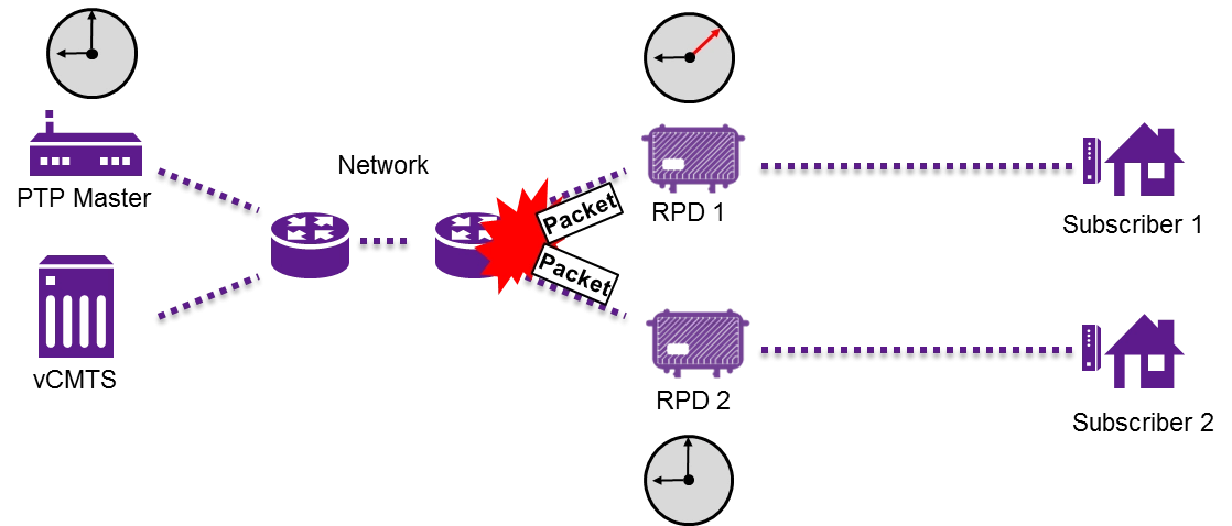
DAA also removes the RF feed from the hub, disallowing the use of traditional dedicated test gear in these locations. This change has a direct impact on actions such as ingress monitoring and remediation, sweep and transmitting leakage tagger signals.

This new DAA technology inflection has also created a proliferation of NEMs in the market giving operators more choices, but also creating confusion and complexity around testing. Many NEMs offer point-solution testing tools that only partially support other vendors gear. This means technicians must be trained and equipped with a wider mix.
DOCSIS 3.1
DOCSIS 3.1 enables more capacity over the same spectrum helping to keep CapEx and OpEx down while greatly increasing throughput. But DOCSIS 3.1 is much more complex than its predecessor, mainly due to orthogonal frequency domain multiplexing (OFDM) and low-density parity check (LDPC). These changes increase the robustness of the plant against impairments but also require new methods of troubleshooting.
One of the key issues for DOCSIS 3.1 are the wider orthogonal frequency division multiple access (OFDM-A) carriers that make upstream ingress detection more difficult. This is mainly due to the fact that using guard bands between carriers to detect ingress is impossible from coverage standpoint since the carriers can be ten or more times wider than single carrier QAM’s (SC-QAM).
Existing test gear is often not capable of performing service testing on DOCSIS 3.1 carriers or testing the full spectrum including the optional frequency extensions that allow up to 204 MHz on the upstream and 1.2 GHz on the downstream. The CableLabs PNM Working Group designed powerful test and measurement capabilities into the DOCSIS 3.1 specification, but back-end systems and field meters must evolve to fully leverage CCAP and customer premise equipment (CPE) as remote monitoring probes.
There will also be a paradigm shift for technicians as DOCSIS 3.1 introduces new metrics and changes conclusions that can be drawn from existing metrics such as correctable codeword errors. Technicians will need to be trained on the new protocol and know what results to look for as well as how to accurately interpret those results.
Continuous Change
The final challenge has nothing to do with a specific technology, but rather how to manage all of the new technologies and legacy systems as the HFC plant goes through continuous change. The path operators take to evolve the HFC will be gradual and inconsistent throughout the plant. Advanced technologies will need to be deployed in certain nodes or regions sooner than others to keep up with demand. Newer sections of plant or areas with low utilization might keep legacy technology longer to keep costs down.
This creates a plant that will be a highly heterogeneous mix of architectures with service provision gear from multiple vendors for at least the next 5-10 years. Operators will face the challenge of trying to standardize plant maintenance methods and procedures while dealing with this new chaotic environment. Technicians will need to be equipped and trained to maintain and troubleshoot a dizzying variety of node permutations.

As new technologies are introduced to the HFC plant, the equipment technicians use and how that equipment interacts with the network to conduct tests will change. In some cases, the solution is as simple as adding accessories to existing testers. This is the case with fiber deep where fiber inspection tools and optical power meter capabilities can be added to existing testers, eliminating the need to purchase additional point solution instruments to fulfill basic fiber test needs.
For DAA, Ethernet test gear designed for CATV is used to validate new Remote PHY device (RPD) turn-ups and troubleshoot timing issues for Remote PHY nodes that split the MAC and PHY layers. Virtualizing the upstream spectral analysis capabilities previously handled by hub-mounted hardware into the RPD enables continuity of these critical capabilities in a DAA environment.
The RPD can further be leveraged to transmit and receive sweep telemetry signaling with existing field sweep meters, enabling a common sweep process between legacy and DAA nodes. In this case, the technician uses the same process and meter regardless of the node type or service provision gear in use effectively insulating the technician from the underlying complexity. Leakage tagger functionality is also virtualized into Remote PHY nodes to enable this critical plant maintenance capability in this new virtualized environment.

For DOCSIS 3.1, smart field meters with automated testing and intuitive user interfaces shield technicians from the underlying complexity of the technology. Some of the newest DOCSIS 3.1 field instruments have dual overlapping FFT analysis and heat map-based displays to enable ingress detection under the OFDM-A carriers as can be seen in the image below.
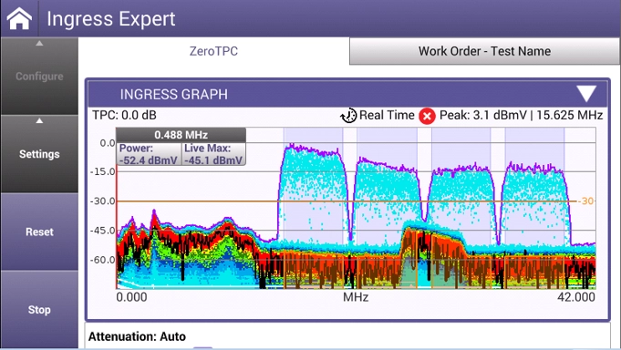
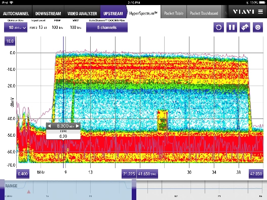
The newest instruments and sweep systems are also fully compliant with the extended DOCSIS 3.1 frequency ranges. This helps technicians accurately assess the plant during pre-turn up and certify the plant after construction is complete. The most advanced instruments are part of a modular family where individual modules can be replaced as technologies change instead of replacing the entire instrument. This will save operators money and simplify changes for technicians since they will continue to use a familiar instrument.
Most recently, new software-based solutions have been created that support technicians by interacting with their field meters to enable a common process – regardless of the underlying plant architecture or network equipment vender that is in use. These systems can monitor the plant, send real-time data to technicians to speed up the mean time to repair (MTTR), and then store the data for future use. This type of system will be vital as the HFC plant continues its complex evolution.
The HFC has evolved to meet ever-increasing market bandwidth and quality demands, but now more than ever, technicians in the field are critical to keeping the plant running at its best and fixing it when it goes down. Loose connectors still need tightened, drops still need to be replaced, and subscribers can’t seem to leave their in-home wiring alone – all issues requiring technicians to address.
Virtualization will enable continuity of critical test functions and increased dispatch accuracy, but once in the field, technicians will still need the best instruments and systems to find and fix issues. The proliferation of architectures and NEMs will make process standardization challenging. Tools which insulate technician operations from this underlying complexity will be critical to success. The rate of change that we will see in the HFC over the next 5-10 years will be unprecedented and will create significant challenges for those who must maintain and troubleshoot the plant. However, with careful planning we can come out the other end with even more efficient and effective plant maintenance processes than ever before.