Fiber to the Antenna (FTTA)
State of the art FTTA testing solutions from VIAVI
")
Service providers, network equipment manufacturers, and contractors work closely together to ensure all FTTA cell sites are installed with the highest quality, and all fiber, coax, and RF interfaces are tested and validated to ensure maximum ROI and QoS.
VIAVI Solutions offers comprehensive wireless installation and commissioning solutions designed to help streamline workflows and simplify account operations with centralized inventory and test equipment management, and consistent presentation of results. Our instruments and meters for FTTA installation offer high durability, ease of use, fast and accurate results, and are approved by most tier-1 service providers.
What is FTTA?
Fiber-to-the-antenna (FTTA) is a wireless site architecture where optical fiber is run all the way up the tower to replace much of what was traditionally completed with heavier coax cabling. Important components such as remote radio units (RRUs) are also positioned at the top of the tower instead of at the base location.
In a FTTA configuration case, a baseband unit (BBU) situated near the bottom of the tower is connected via a fiber optic antenna and runs to a remote radio head (RRH) positioned near the antennas at the top of the tower. The RRH converts the digital signals to analog, and the short span between RRH and antenna is still completed using traditional coax cabling.

Tips for Installing FTTA
If customers don't get online, then contractors don't get paid. That's what happens when a new cell site isn't installed properly. And that's why every fiber-to-the-antenna (FTTA) cell site deployment must follow a strict high standard of quality, administering attention to all details throughout the process. All cables and connectors—whether coax, fiber, or twisted pair—must be thoroughly certified. Every active and passive component in the antenna and cable system must be properly tested and performance-validated.
Resources:
- FTTA Installation and Maintenance Testing Quick Start Guide, Vol. 1
- FTTA Installation and Maintenance Testing Quick Start Guide, Vol. 2
- On-demand webinars below – learn from VIAVI experts why, and how, to conduct these critical tests for FTTA installation, and the tools you need to do it right the first time, every time.
Webinar Series: FTTA Installation
Watch these webinars to learn about the required tests for FTTA installation, why they're critical, and how to conduct them.
Click the "Read More" button below to view the transcript
Related Resources:
Essentials of Fiber to the Antenna: Fiber Inspection and Connectivity
Hello and welcome to VIAVI Solutions webinar series on fiber to the antenna installation. This webinar will cover fiber inspection and connectivity.
Let's go ahead and jump in and get started. The first thing I want to do is take a closer look specifically at the connector itself. What we have here on the right is a picture of a fiber connector very close up. I wanted to just specify what you're looking at when you see a fiber connector.
I've highlighted a couple of three areas here, the core, the cladding, and the ferrule. I'll go through those in reverse order just to clarify what we're talking about. The first is the ferrule. This is usually the piece that oftentimes gets confused by many people as the fiber itself. It's not the fiber, it's that component that actually houses the fiber and keeps it in place. It's made out of ceramic most often in a single fiber connector and it's the part that protrudes out of the different connectors. They're typically either 1.25 millimeters or 2.5 millimeters depending on the connector type. We'll go over that in a few slides here.
The next is actually the fiber itself. That fiber contains two main elements, one is called the cladding. This is actually a protective outside layer that houses the fiber itself. Then inside that cladding is the core. That's actually where the light gets transmitted, depending on whether you're dealing with a single mode or a multi-mode fiber, that core size can vary. In a single mode fiber, which is what we're looking at in this example, it's about 9 microns whereas in a multi-mode fiber it's usually 50 or 62.5 microns, most common today is 50 microns.
You'll see in this illustration here that it shows the fiber actually protruding out, highlighting the core and the cladding. That's actually not what you'd normally but I added this in just for visual representation of where you'd actually find the true fiber in that connector. The next thing I want to do is take a look more closely at that fiber end face. In order to do that we're going to need to use the support of a dedicated fiber optic inspection microscope.
Here we go, here's a closeup image of that fiber end face. Now you can see here, I've highlighted in this view through a microscope the ferrule itself, you'll see, is typically white. It's this ceramic material here on the outside. The cladding is the outside part of this fiber here, this big circle is the fiber itself, the dark gray portion is the protective cladding, and then the core, where the light transmits through, is here in the center. As I had mentioned before, this is a single mode fiber so it's a small 9 micron circle. If you were to shine light on the other side through a visual fault locator or something this is the portion that you would see actually glowing.
You'll also notice in this image here that there are a number of different dark spots or flakes. Those are actually contamination debris and we'll go into that in much greater detail in the slides to follow. In the next slide I want to specifically call out two different fiber types that are very common today. The first is single fiber, the other is multi-fiber connectors.
Now with single fiber connectors it's just like it's described, it's one single connector has one single fiber in that. When you look through that with a microscopic view, just like we showed in the last slide which had a single mode fiber, this one here shows a multi-mode fiber, so you'll notice the core is slightly larger here, it's 50 microns. It is one fiber per connector. The common types that you'll see of single fiber connectors are LC, SC, FC, or ST which are less common today. The most common are SC and LC and we'll look at those in greater detail in some slides to follow.
The other one I want to highlight is a multi-fiber connector. This is actually where you have one single connector but it includes several fibers all inside that connector. You can see here in this microscopic view, here is a view of the end face. You'll notice immediately that the ferrule itself actually no longer is white, it actually is much darker looking. That's going to the material is made out of a combination of polymer with little glass pieces embedded into that for strength so that's much darker. The other big thing is that it actually has multiple fibers in a single linear array.
In this microscopic view here you can see two of those fibers but if you were to scan across you would actually see anywhere from eight to 12, 24, 48, and even in some cases 72 fibers. Oftentimes in a cell tower or an FTTA application you could see 12 fibers. The most common type that you'll see there, it's called an MPO connector. You'll sometimes hear the term MTP, that's a specific brand of an MPO connector. Those are occasionally seen in an FTTA application. Frankly the most common fiber connector you'll see in FTTA environments are still single fiber connectors, usually LC or SC.
Let's take a closer look at those single fiber connectors and the different types. I've mentioned LC and SC, these are two that are highlighted on the left here. An LC connector is the fastest growing connector we're seeing on the market, it's been around for several years now. These are very popular going to of their compact size. They have a 1.25 millimeter ferrule and the latch is a finger latch or it's very similar to what you see in an RJ45 style connection jack that you have on your typical copper input on the side of your PC or something.
Next is the SC connector. These are very popular and have been prevalent for many years. They're slightly larger than an LC connector, they have a 2.5 millimeter ferrule and they're connected using a simple push-pull latching mechanism. If you want to disconnect that you just grab onto the plastic housing and pull that out and that'll remove it. To connect it back in you just press it in and it'll click into place. Both of these connectors have a keying mechanism, you can see here on the top of these SC connectors. That controls the orientation that it's plugged in. Here on an LC connector it's done through that latch on the top.
Other common types are FC connector, this is also using a 2.5 millimeter ferrule. It threads on in a typical bayonet style or a screw type fashion. An ST connector, which is a twist mechanism, so it's like a bayonet style connection. You press that in and you give about a quarter turn and that latches that into place. Those two are less common. Most of what you'll see in an FTTA application is an SC or an LC.
Next I want to explain how a fiber connection actually works and we'll take a close look at the cross section of an LC connector. Here is a side view of what is actually going on when you make a connection. Both connectors in LC on the front end and the back end are the same and how they're joined is by the use of a bulkhead adaptor. Typically in an FTTA application, whether you're at the bottom of the tower or at the top, you'll only see one side of that connection. You'll see the bulkhead adaptor and you won't be actually able to see that connector behind the bulkhead, it's usually inside of a housing or something. This cross section view gives you a better understanding of what's going on.
That bulkhead adaptor has an alignment sleeve in it typically made out of ceramic. It is actually used to control the correct location and alignment of the two fiber ferrules. It allows you to actually line up the two cores so that they're specifically in place. It also houses the latches of the LC connector so that they snap into place. What happens when you add that second connector into it is it comes in, it clicks into place and physical contact will actually take place between the end faces of those two connectors. That's the joining point where the fiber light will actually pass through.
Let's take an even closer look at what's going on when those two connectors make physical contact. Here at the bottom is a very close look at that fiber ferrule itself and what's going on there. You can see this is actually the core and the cladding of the fiber. What happens is when you make physical contact if any dirt or debris or contamination is introduced into that connection, now you have a bad connection. Typically when you use that alignment sleeve that controls both the core alignment and gives good physical contact. Those are two things that are very well controlled by the manufacturers of the connectors and the bulkhead adapters and such.
The other thing that can go wrong here is the end face. If it's not pristine you're going to compromise the integrity of that connection. Not only will physical contact be prevented, you'll also lead to back reflection that actually sends part of that optical signal back to the source of where it came from. You are now introducing both insertion loss, so the amount of that optical power that you're sending over is going to get compromised, and second, a lot of that power will get sent back into the source where it came from itself. Introducing a single fiber into that connection causes significant detrimental impact.
To expand on what we mean by detrimental impact I want to describe this by using an OTDR. This is a way of measuring the optical power of an optical connection. Usually every time an event occurs it'll actually measure the amount of loss that takes place at every single connection. What I have here is a trace showing a couple of events that utilize an OTDR. The first here shows a trace with a connection and the loss here is very minimal, less than .25 dB and very reasonable back reflection. The second event also is very similar to that. In events one and two those have clean connections.
Event there here, you can see a couple things happen. One is there's a big spike here that's representing that there's a high amount of back reflection. Second, there's a significant amount of loss that occurs, actually nearly 5 dB of loss. That loss is caused going to of the contamination that was introduced onto that connection here of the end face of that fiber. Let's take a closer look now about what are the different things that can go wrong and how common fiber contamination is.
Here are some of the most common causes of network downtime. You can see here that I highlighted in red the most common cause actually is contaminated or damaged connector fiber end faces. This here is why we're dedicating an entire course here in this series to this topic, going to it really is the number one cause of problems in a network. We want to highlight why that happens and how you can prevent that. The underlying cause of that is going to of a contamination and you can solve that simply by inspecting it, cleaning it, and re-inspecting it. If you're ignoring that practice you are definitely going to have problems with contamination on the end faces of the connectors.
Other things can go wrong as well, physical stress on the fiber caused by what are called macro-bends, this is over-bending the fiber. You can also have loss caused by micro-bends, this is like where if somebody were to have stapled the fiber onto a board or over tightened a zip tie or something like that and that causes a micro-bend. These are all causes as well. Bad splices, physical stress on the fiber, as I mentioned with micro-bends. Exceeding link loss, the length of your fiber, wrong fiber types being used, damage to the transceiver and such. Again, the number one cause, the majority by far, 80%, 90% depending on who you talk to the root cause is isolated down to contamination on the end face of the fiber.
Again, this is just a microscopic view. If you were to inspect that fiber you'd find contamination on the end of that. We're going to now describe to you how you can actually address this issue. At VIAVI we use the term inspect before you connect. This is just a rule that we like to emphasize as a best practice for whenever you're handling fiber. This diagram here is a very simple process flow diagram that, if followed, you can eliminate the problems associated with contamination on fibers.
Just walking through this it starts off by inspecting the connector. You ask the question, is it clean or not? If it's contaminated then what you want to do is clean that. Use a purpose-built cleaning tool, not your shirt or not a cloth or anything like that, but there are a lot of dedicated purpose built cleaning tools that are very easy and intuitive to use. We oftentimes include many of them in our kits themselves but they're available through any distributor of fiber optic connectivity.
Once you clean that, however, it's highly important that you reinspect it again. While all of these are good cleaning tools the only way to really verify that you've removed all the contamination is to reinspect it again. If it's clean at that point then it'll look like the image on the right and then you can proceed forward to connecting.
A question here, where does fiber inspection occur today? This here is a cross section overview of all the different places where fiber connectivity is present, whether that be in long haul applications, whether that be inside buildings and enterprises, whether that be in backhaul applications or at cell sites and FTTA locations, or even in building DAS environments.
In short I'll give you a clue, these are all places where fiber optic connectivity is present. If fiber optic connectivity is present there those are all places where connections can happen, so therefore those are all places where connections can get contaminated. The short answer is everywhere, anyplace that a fiber optic connection takes place, that's where fiber inspection should also take place.
Let's take a closer look at what this means. How is fiber inspection actually performed? When we talk about inspect before you connect there's a couple of things associated with that. Number one, this means there's two sides to every connection. That means that you need to inspect both of those sides. A common mistake that is oftentimes made is people will use a simple microscope to inspect the patch cord before the plug it into the bulkhead port. That's very important but it's also important to check the connector behind the bulkhead as well. Every connection has two sides so while it may be easiest with a very simple microscope to check that patch cord you also need to be able to inspect the connector located behind that bulkhead.
Here's an image showing an inspection microscope and a video display that demonstrates both of these sides being inspected. You can see the image on the left, it's plugged into a dedicated inspection microscope on the display, that's inspecting the patch cord itself. Then you also will have the connector located behind the bulkhead. That can only be performed using a probe microscope that has a special tip attached to the end of it that'll allow you to plug that into the bulkhead to be able to make that inspection. Here is an example of what it looks like to inspect both the patch cord and the bulkhead.
The next question that I'll often come across by people is how clean is clean enough? Pristine is obviously ideal but there could be questions of does it always have to be pristine? Is there any standard out there? The short answer is yes, there actually is. A couple of years ago the IEC, global standards body, issued a standard, the 61300-3-35 standard. That communicates very clear criteria for how clean is clean enough. What the standard has done is it provides inspection criteria based off of a series of zones. These zones are basically concentric circles, very similar to an archery target or something. The closer you get to the core, where the light is transmitted, the stricter the acceptance criteria is.
You can see here in zone A, which is known as the core zone, it calls out no contamination at all should be allowed to be present in that particular zone. Then as you go farther out it starts to get a little bit more lenient, say in zone B where the cladding is. For this particular criteria, which is for single mode fibers, it'll say anything smaller than 3 microns is acceptable, anything larger than 3 microns we will not accept, anything from 2 to 5 microns we'll allow up to five. There's some very strict criteria that go along with this.
Frankly speaking this can be very difficult to be the judge of if you're just looking at that and making a judgment call just through visual observation. We call that subjective inspection going to two or three people can look at that and each person could have a different opinion on whether that's acceptable or not. I should also point out that this acceptance criteria, there are specific criteria for different kinds of connectors. If you've got single mode fiber there is a specific set of criteria for that. If you have multi-mode fiber there's specific criteria. If you have multi-fiber, like an MPO connector, there's specific criteria for that. Adhering to all of these, there are criteria available.
Many installation technicians, especially in an enterprise application, will require that this criteria be adhered to. Service providers do the same thing and this is making its way also into FTTA applications as well. When new fiber is installed oftentimes the technician is required to provide proof that it meets this standard before they can certify that that installation was complete. Again, this is very subjective.
One of the challenges that oftentimes technicians have is ... Say, looking at this fiber here, if they were a cell technician and they were about to leave this site and show that all the fibers were installed and read to be connected by the next person who's going to activate this ... If they were to leave this fiber as it is they might ... They're leaving themselves vulnerable going to they don't have any proof that shows whether this passed or failed. If the next technician coming in comes in to make this connection and they end up finding a problem with that they'll oftentimes go back to that installation technician and say, "This was your fault, you didn't provide any proof that this was clean or not. What criteria did you use to judge to that?"
Here's an example of subjective inspection. If somebody were to look at this and they were to ask the question, is that acceptable or not? I could look at that and say yeah, I think that looks pretty good. However if you were to use an objective pass/fail tool to evaluate this you would find that this actually failed based off of the IEC inspection criteria. When I refer to objective inspection what I mean is there are microscopes available now, and they're very prevalent in the market, to make objective inspection easier by automating this with an automated analysis capability built into the microscope. Now all you need to do is press a button on the microscope and it'll evaluate the end face of that fiber connector based off of the IEC inspection criteria or user specified or customer specified criteria and evaluate it to determine whether that passed or failed.
In this situation here, if you didn't check this one you might be leaving yourself vulnerable to the installation technician at the end who is going to make the final connections. If they had a problem they could point this back to you as a technician, to say, "Hey, you gave us a fiber that did not meet the inspection criteria so we're going to charge the added labor back to you." Having an objective inspection microscope is really the best way to prove the quality of your work and eliminate any vulnerability that you may have. The other thing is it's very quick, all you have to do is press the button and it'll perform that focus and analysis in a matter of just a few seconds. Then you're done and you can generate a certification report providing proof that that's all done.
Next I wanted to take a close look at what does this look like on a cell tower in an FTTA environment. There are a couple of places where fiber connections actually take place. I know there's a number of different scenarios but I just wanted to highlight a couple of examples here about where this is the most common. At a cell tower you're going to see connections at the bottom of the tower and also at the top. Oftentimes the technician at the bottom, what they're required to do is to provide a very simple length loss test just to make sure that they're meeting the loss budget of the fiber that's run up that tower so they want to plug in an optical source and a power meter and just measure the loss budget to make sure that everything is okay.
Again, anytime that they're handling fiber it's important to make sure you inspect that fiber first. There are a couple places at the bottom of the tower where you're going to want to inspect that before you even plug into your fiber test measurement equipment. First is the end of your jumpers that you plug into the BBU, the broadband base unit. Second is the jumpers that get plugged into the junction box. Then third is the end of the trunk that is plugged into the junction box as well. I realize that various FTTA sites may look different than this but these are some examples of where some fiber connections take place at the bottom of the tower.
Every time you make that connection at the bottom you're going to want to make sure that you inspect those and validate that they're clean before you plug them in. You also want to make sure that you do that so you don't damage the equipment of the broadband base unit or the junction box going to those, if they're damaged you're going to have to send somebody else out to make those repairs.
Second is actually at the top of the tower. Once I have a technician that climbs to the top, oftentimes they'll use a loopback, sending the signal back down to the tower. You want to make sure that you inspect the loopback and that connector that plugs into the loopback as well to make sure that those are clean. I've included this image here on the right. This particular image is not of a cell tower but it shows the technician climbing a pole for a fiber to the home application.
The scenario is the same with regards to ... That technician is at the top of a tower, they don't have much to work with. One of the things that's kind of convenient about using a fiber inspection microscope is we've got hands-free carriers so that you can focus on the safety of the technician, holding onto the ladder, keeping yourself secure. The inspection microscope is in a hands-free carrier that's around your neck so you don't have to use a hand to hold onto that. The other hand, then, you're using is to hold the probe microscope. You want to make sure that you inspect both sides and you want to inspect at the bottom of the tower and at the top of the tower.
Next I just wanted to highlight a couple of the different inspection products that are available in the VIAVI portfolio. The most basic one is a simple P5000i probe microscope. This can plug into various handheld test equipment that we have. It also can plug into your mobile device. This microscope as well as everything here can perform that pass/fail analysis that I was talking about. There are also dual magnification microscopes and they're compatible with various mobile devices.
Next is any SmartClass Fiber device. When that technician there was looking at ... Climbed at the top of the tower and had that hands-free carrier, this is what that technician was using. It's got a built in pass/fail analysis to it and it also has a built in dedicated microscope for patch cord inspection. This is very convenient going to if you want to inspect the bulkhead and the patch cord you don't have to mess around on the probe microscope, changing a tip interface or anything like that to inspect the different kinds. You can plug the patch cord into that dedicated patch cord microscope on the video display and then you can use the probe for dedicated bulkhead inspection.
Next is the FiberChek probe microscope. This is a real convenient microscope going to everything is all built into one system. It's got a built in touchscreen display, it performs the pass/fail analysis. If you wanted to connect with mobile devices it can do that over Bluetooth or WiFi, so there's a lot of conveniences there. It'll store all the results right on the device and you can export those, connect them to your mobile device or a PC later on.
Last is the FiberChek Sidewinder. This is primarily advantageous for inspecting MPO or those multi-fiber connectors. Both the FiberChek and the P5000i will also inspect multi-fiber connectors but they do that one fiber at a time, so there's a dedicated tip that goes on the end of that microscope that has a scrolling wheel on that and it'll allow you to inspect each of those, let's say, 12 fibers by performing inspection or even pass/fail analysis of each one of those as you scroll across. Whereas with the FiberChek Sidewinder, it automates all of that so if you are dealing with MPO ribbon connectors and high volume you can plug that in, press a button, and it'll automatically scan across all of those, let's say, 12 fibers and give you a pass/fail analysis result in a matter of 12 to 15 seconds and you've got all of those results.
That's just an overview of some of the different inspection microscopes that are available in the VIAVI portfolio, each one really having dedicated benefits depending on what your purpose is and what your budget is. Last I just wanted to highlight some of the resources where you can find out more. In addition to this short presentation here we have several educational videos. We have a dedicated page on our website that all of these FTTA resources are available. In addition to that fiber inspection has a number of resources so you can always go to a dedicated page we have online at "What is Fiber Inspection?". The FTTA page provides a link to this but you can always just go directly there.
When you're there you'll find a number of links and resources, including a 14 part video series specifically talking about this inspect before you connect practice and going into detail of various attributes about why you'd want to inspect both sides, or why you'd want to inspect our test leads, or keeping the ports on your test equipment clean, which cleaning tools are the best for your application ... All of those are very short three to five minute videos that explain how you can best incorporate this practice into your fiber handling methods.
We also have a series of what we call quick tip videos. These are product specific of all the different products that I just highlighted for you. We walk through how to use this equipment and how to get the most out of those and what those benefits are. We also have a number of other educational resources, whether they be posters, blogs, articles, things like that. All of those are also available on our "What is Fiber Inspection?".
Click the "Read More" button below to view the transcript
Related Resources:
Essentials of Fiber to the Antenna: Cable and Antenna Testing
Hello and welcome to VIAVI Solutions webinar series on fiber to the antenna (FTTA) installation. This webinar will cover cable and antenna testing. To access all of the webinars and related material please visit FTTA.
Let's get started.
Cable and antenna systems remain the cause of many cell malfunctions today. It is estimated that more than 70% of problems in base stations are in fact related to the cable and antenna systems. There are many reasons for this to be the case. Among all those, for example, components can get damaged due to weather conditions, including lightning, weather intrusion, corrosion. In other instances, the problems can be caused by items not being installed properly, like swap antennas, loose connectors, improper torqueing, and similar things.
The best time to identify many of these problems is during the commissioning stage, right after installation has taken place, but before the new FTTA cell site becomes active; however, regular maintenance and testing of these elements is required to identify new uses and fix this before they have an impact in the overall level of performance. Like for example, a reduction of the cell site coverage, slow throughputs, and so.
There are a few key measurements to detect and resolve these problems associated to cable and antenna systems. For example, we have Return Loss of VSWR, Distance to Fault, Insertion Loss, RF power measurements. During this presentation, we will look in more detail into these metrics and how to effectively measure it. Through this presentation, we'll go around two concepts that may replicate in diverse ways. One is signal reflection and the other is the concept of signal loss, which is typically referred as a form of signal attenuation. Reflection and loss in RF transmission can be compared to what happens when a light wave crosses a lens, where part of the incident light will be reflected by the lens, sort of a mirror effect, if you want. The part of the light that is being absorbed by the lens is actually can be attenuated as well.
Signal reflection is referred to the amount of energy or power that gets reflected by the cable and antenna system when the main communication signal is transmitted through this system. Different components may cause reflection back to the main source. Reflections are in fact an unwanted behavior for any communication system. Also, the other result of impedance mismatching through the FID line by different elements like cable jumpers, connectors, adapters, up to the transmitting antenna. The main consideration is that any amount of energy that gets reflected is in fact not being transmitted by the antenna, which results in a waste of energy by the transmission system and underused network performance. For example, the less energy being transmitted, the less coverage the cell site will provide.
On the other hand, the effect of attenuation is sometimes referred also as cable loss. However it's important to notice that not only cables but all the components can also introduce attenuation, and so reduce the level of signal power being transmitted and the end compared to the power of the original signal at the source. Generally speaking, cable and antenna analysis measure the ratios of reflected and transmitted signals to the original incident one that we were intending to transmit.
Another critical point is the one related to the calibration of the cable and antenna analyzer before we can perform any measurement in the field. Calibration is required so we can compare normalized the resource of the measurements of cable and antenna system with those of known references. These references are provided by the so-called calibration kits, that typically include 3 different references, an "open" that emulates the transmission system with an open end, a "short" one that emulates shortcuts, and a "load" that provides the 50 ohm reference, that is useful, the one that we use in these outside systems.
There are two categories of calibration kits these days, one is referred to as the mechanical one, that includes each reference in a different port connector, with the use and the needs to change and connect during the calibration procedure. The other category is referred as the electronic calibrator which includes only one connection port and the switching between different references is done electronically through an internal secretary, typically controlled by the test analyzer through a USB controlling cable.
Once proper calibration has been performed, it is possible to proceed with signal reflection measurements through the entire cable and antenna system. There are two different standardized metrics that are used by technicians in the field to measure signal reflection. One is called Return Loss, and the other is VSWR, which stands for voltage standing wave ratio. As a matter of fact, both metrics indicate how well the cable and antenna system is matched in terms of impedance. VSWR is also a measure of how efficiently RF power is being transmitted through the transmission line and into the end-load.
Note that return loss is measuring dBs while VSWR is a measure of value number in relation to 1. In the ideal situation that an antenna and cable system is capable of transmitting all the power originated at the source, that means without any reflection or loss, the VSWR, one to one, and the return loss will be at the infinity volume. On an opposite example, if a transmission system was reflecting, say 97% of the incident power, almost the total reflection, basically. Then the VSWR in this case could go as far as 65 to 1, and the return loss might be only 0.26 dB, a terrible value for any transmission system.
Regardless, if you prefer to measure reflection in terms of VSWR or as a return loss value, the good news is that modern cable and antenna analyzers support both types of metrics and in fact with tools like the VIAVI Solutions JD720C Series. You can even visualize both measurements in parallel, in a single dual-mode screen, like in this example. Note how VSWR return loss in this example are always measured for a specific frequency range, which is intended to be the typical operating range of the transmission system of interest. For example, if you were to measure a cell site transmitting GSM technology in 900 MHz, you will be configuring your reflection test for that specific frequency range around 900 MHz. And also your previous calibration steps will have been completed at that same frequency range for maximum test result accuracy.
Distance to Fault is another important measurement helps to identify any possible elements in the cable and antenna system that are producing the largest signal reflections, which could be impacting negatively the performance of the signal transmission. Distance to Fault measures four locations in the transmission system of the cell site, indicating where are the biggest signal discontinuities in terms of VSWR or Return Loss. Note however that Distance to Fault is a measurement in the time domain as opposed to VSWR that operates in the frequency domain as we just mentioned before. Going to the technician has also access to the propagation velocity specifications of the cables installing the cell site, the distance to the faulty element is easily calculated as the result of that velocity by the time measure. Modern cable and antenna analyzers include databases of several hundreds of cable types, which automatically factors in the relative propagation velocity into the Distance to Fault measurement.
As shown in this measurement example, the Distance to Fault can be presented in the format of VSWR or as a Return Loss, or even as both metrics simultaneously, if required. Note how these are now measured for a specific distance range, instead of a frequency range. The distance value, where main discontinuities marked, indicates the position in the cable and antenna system where the corporate element is located through the feeding line from the source where the test unit is placed. When the given network component is identified as the faulty element, for example, a cable jumper, a connector, or an adaptor, the technician can proceed to the replacement of that element or else to fix it on the spot if it happens to be just a loose connector or similar.
So far, the previous measurements that we have discussed have all been related to the overall performance of the entire cable and antenna system. However, sometimes it is important to confirm the individual contribution in terms of attenuation or gain that comes from a single individual component within that entire system. This individual item measurement is often referred as cable loss or insertion loss. Note that when we say "loss" in this context, it is meant as an attenuation, something that weakens the original signal power. But in the opposite way, certain active elements like the amplifiers for example, can also introduce a gain on top of the original signal power, which in fact is the opposite of a loss. In terms of measuring loss or gain, the elements of a given cable and antenna system can be classified as 1-port or 2-port elements. A typical 1-port element is the cable jumper, which is measured only on one side, which 2-port elements include instead an input and an output port that need to be connected to the cable and antenna analyzer. Examples of 2-port components are filters, attenuators, amplifiers, and similar.
This example shows the measurement for a 1-port element, and is also commonly referred as Cable Loss Measurement. In the screenshot, you can see how a Pass/Fail threshold marks indicate the range of frequencies for which this cable presents the maximum attenuation values. Indeed, the loss figure for many components changes at different frequency ranges, which is an important consideration as you want to make sure your cable loss is minimal at the specific frequency ranges that the cell site needs to operate. Another related measurement is the 1-Port Phase that can help technicians with systems tuning the antenna element in particular, for example.
This other example shows a 2-Port measurement applied to a type of element called TMA, or Tower Mounted Amplifier. Amplifiers have the ability to increase the power at the output of the received signal in the input. This is often referred as adding a gain to the signal. This 2-Port measurement allows to validate how much gain in fact, a given amplifier, is providing. And if that gain is within expected or desired values or else, if the amplifier is no longer operating at the specified gain levels. As with many other types of measurements, the 2-Port gain or loss is always related to a given frequency range. To test our mounted amplifier, a special feature called Bias Tee is usually required. The Bias Tee is a function available in many cable and antenna analyzers that allows us to inject a DC signal into the amplifier to activate the amplifying of the signal received at the input port.
Moving into a different aspect of FTTA cell site testing, the RF power measurement allows to validate the total RF power being transmitted into the cable and antenna system. There are two types of power sensors that can be used for this purpose. One is the so-called Terminating Power Sensor, where the sensor interrupts the power transmission, effectively disconnecting the cable and antenna system from the transmitter and absorbs all the power to measure it. To prevent damaging the sensor, this procedure usually requires the use of an external attenuator device. The other is the so-called Directional Power Sensor, which connects in between the transmitter and the cable and antenna system and measures the transmitting power without the need to interrupt the transmission service.
Also important today is the ability to control remotely the device and the ability to generate different types of reports, including the location of GPS information into that report. Modern tools like the VIAVI Solutions JD720C allow to control the device over Bluetooth or Wi-Fi or even ethernet, or a network, and also provide GPS location stamps for all the measurements, including the ability to generate configurable PDF reports.
VIAVI Solutions TestWizard is another utility that allows managers to graphically create FTTA test procedures for example, for methods of procedures and distribute these through a free cloud service to all the cell technicians in the field for reliable and convenient systematic testing. The advantages of this systematic approach to testing in the field is that all the technicians basically are now with a set of guidelines in conformance with a mobile operator Pass/Fail criteria. Also, this self-guided test sequence indicated by the instrument, which minimizes the need for training or product certification. The final results after each test are automatically uploaded into the StrataSync cloud service, expediting the installation and maintenance best practices in cell sites.
The VIAVI StrataSync cloud service is free with any VIAVI Solutions product and allows to do asset management, managing and tracking the whereabouts of all the test instruments in the field. This includes, by the way, an anti-theft mode that blocks the instrument in case of being stolen. Data management, which collects test results from the entire network and uploads those results automatically in a central repository. Also, notifies users of new firmware releases and product options available through VIAVI updating system.
VIAVI Solutions Portfolio for cable and antenna analyzers include different options covering different frequency ranges from a basic 2.7 GHz up to 4 GHz or even 6 GHz, with one or two-port measuring capabilities. These instruments allow for insertion and gain/loss measuring, cable and antenna analysis in general, RF power metering, optical power metering, fiber inspection, and includes additional options like the TestWizard, remote control, and cloud services we've just mentioned.
There is a number of VIAVI RF Test educational resources available to customers through our website, this includes Application Notes, like antenna isolation testing with CellAdvisor, analyzing Distance to Fault and VSWR efficiently with the CellAdvisor JD720C series. We have an excellent e-book to go through all the different aspects of commissioning of fiber-to-the-antenna (FTTA) cell sites. We have posters available that show the different items that require for installation maintenance of a cell site. We have a number of case studies as well and product briefs and brochures. More information and access to all these documentation is available on cell site installation for your reference.
Click the "Read More" button below to view the transcript
Related Resources:
Essentials of Fiber to the Antenna: Fronthaul Installation Test
Hello and welcome to VIAVI Solutions webinar series on fiber to the antenna (FTTA) installation. This webinar will cover fronthaul test.
Let's get started. We're going to be looking at some of the issues, or some of the things that we will be encountering during a fronthaul installation.
So if you take a look at what the fronthaul lifecycle looks like, we really need to understand the needs behind the fronthaul. The construction or installation of the FTTA fronthaul is definitely not the first phase, and it's really, if done properly or as done properly, you need to cycle through and go through initial construction, installation as equipment gets improved throughout the years, every time you do that, you need to have a commissioning/acceptance phase. Then after acceptance it goes into maintenance mode where primarily you'll be just doing troubleshooting, maybe some add/deletes.
Ideally you'd be looking at some optimization and then you're probably back to leveraging the current construction that has been in place and doing additional FTTA installations.
A significant amount of planning went into the site selection. So there are a significant number of parameters that need to be configured during the installation phase of the fronthaul.
If you look at installation, it's typically performed by multiple teams cooperating with each other to deliver a high-quality site/installation. And at the end of that step, the commissioning/acceptance phase verifies the construction is complete, the installation is complete before putting the site into maintenance.
So if we take a look at the deployment lifecycle and the working groups that are involved, during the construction phase, if the tower doesn't already exist, or the pole, or the site doesn't already exist, of course you have go ahead and erect the tower. But there's also a phase where construction team rigors come in, they install fiber to the top of the tower, or top of the pole, or top of the roof. They mound the remote radio head and of course any other item that needs to be put it, such as electrical power, satellite antennas, and so on and so forth.
During the second step a cell site technician or a technician/engineer under contract provided by the network equipment manufacturer or a subcontractor comes in an installs what's known in 4G LTE parlance as the BBU, the baseband unit. Switches and routers are installed. The baseband is connected to the remote radio head, which was installed during step one, and the backhaul is connected for the first time.
And then at that point, you go into the acceptance/commissioning phase, or the acceptance of the FTTA site, or either a cell site technician comes and runs a set of tests to verify that everything was correctly installed, or reports generated by the commissioning activity and the installation activity are handed off and reviewed to ensure that everything is working properly. And then finally in step four is when you make that crossover to the maintenance phase.
So what challenges are typically faced when installing the FTTA fronthaul? And the answer to that is going to be driven by who you ask or who's perspective you're looking at. So if you take a look at it from the service provider perspective, their point of consternation is usually consistency and testing. They want to make sure that everything is tested properly to hopefully increase the installation quality and avoid any maintenance problems from the start. Optimizing and of course improving the installation process, hopefully reduces delays.
So from this perspective the installation quality and the short delays are important, but the installation quality has a couple of components to it. If the service provider themselves are going to be doing maintenance on the cell site, then of course they want to get something that comes in clean. If the maintenance is going to be contracted out to a third-party, maybe the same organization that was the prime contractor for the installation may be someone different, you still want to make sure that it was quality installation, going to your users' service will be affected if it was not.
And lastly, I guess the service provider amongst their top concerns is improving the contractor efficiency as well, so they don't have to not just take long delays, but also have the installation process be as costly as it is.
From the contractor perspective, you want to improve the quality of the work to reduce free rework. Now, it's not really free rework, it's getting the job done right, but as an installation company, you want to make sure that the number of times that you have to touch the same installation, the same circuit, the same fiber, and touch it again and again until you get it right is reduced, going to it's just not very efficient and that cuts into the bottom line.
You also want to make sure that the documentation deliverables are easy to produce, so that you can accelerate the close-out of the ticket or the close-out of the activity, and can turn around and accelerate the speed at which you deliver proof of completion to the service provider so you can have that ticker start as far as receiving payment.
You also want to improve efficiency so you can in general improve project profitability, whether you pass that on or not to the service provider.
So if we take a look at FTTA fronthaul installation, it's very complex. It's a very complex job to do it right. Yeah, you're putting a remote radio head at the top of the tower, you're feeding a fiber optic, you're connecting it to a few junction boxes, that's not a big deal. This is the step one process, right?
So when we look at step one, you tend to see everything not obfuscated by the purple as being done in step one. And you could see that there's a whole bunch of different things that are important to do. For example, the fiber, it's important that you inspect the fiber to make sure that it's clean, going to if it's not clean and you connect a couple fibers together, you'll be causing permanent damage to the fiber that in the future will hamper its usability or reusability. And if you happen to try to reuse it and reconfigure the speed on it, increase the speed of data that you're passing across that fiber, you could very well find yourself in a situation where you start taking bit errors.
Additionally, you should attach an OTDR, and test for insertion loss, reflectance, optical power, any impairments. And that will probably be the best way you can go ahead and certify that everything from the RRA to all the way down to baseband unit has fiber-wise physical layer installation-wise has been properly performed.
After that's done, then really you go into the next phase where you go in and start verifying that the remote radio head has been properly configured and is working properly. So some of the things that you would look at is the antenna tilt, the VSWR. You probably want to log into the remote radio head and check that the optic that it has is correct, that it's running the correct firmware version, and all that basic stuff, as well as leverage the fact that the antenna is already installed and the remote radio head is already installed, and do a little bit of PIM detection to see if there's inner modulation problems, some interference analysis, check for diversity and balance.
Lastly if you're also installing a satellite antenna, you want to make sure that that satellite antenna has a clear view of the sky over a long period of time and can see multiple satellites.
Now, all that is typically done as a step one type of installation. Sometimes step one installation may also include the installation of a microwave backup, in case you do not have fiber going to that cell site. If you're installing microwave, there are additional series of tests that are prudent to run to make sure that everything is configured properly and that everything will be running cleanly.
So going to of the complexity of an FTTA cell site fronthaul installation, we really recommend an all-in-one type solution such as a T-BERD 5882 with different additions to it such as the OTDR as a fiber microscope, and a job manager that can track all the different tests that you need to run, grab the results, and be ready to generate a summary-close out report. Usually, all these series of tests, even though they seem very daunting, could be done in 30 minutes or less.
So let's take a look at what the Job Manager actually is. It's a workflow tool that's included with TBERD-5800 at no additional cost. And what it does is it executes test plans that have been created prior to going to a job site, making it easy to load, test templates, and making it easy to have customizable job guidance to make sure that there are no tests that get forgotten, and therefore that the testing is as complete as possible, and the quality of the job is as high as it can be.
It also helps improve efficiency going to if you follow all the tests that have to be done in the Job Manager, it gives you a certain sense of repeatability, both if you're testing the cell site multiple times, going back to the cell site, testing it, and once it's in maintenance phase, going to there was a change, there was a problem, etc. or cell site to cell site to make sure that all the cell sites have been installed with the same procedure that has improved the quality.
It also makes it easy to close out jobs by creating summary reports from all the different multiple tests that need to be performed. And mind you, some of the tests, for example you go in and you apply a fiber microscope to a piece of fiber, you see that it's dirty, you have to stop, clean it, test it again, make sure it's clean, and repeat that multiple times with multiple fibers going up to multiple antenna sectors, until you get them all clean. So that could be relatively tedious, but the Job Manager makes sure that you follow through and you do all those tests, and it collect the results from multiple reports.
The Job Manager is really not required to run a test. So if you want to go off in your own direction, or run into a problem that's particularly different, or that deviates a lot from what you would typically do, then you can actually turn the job manager off and run whatever tests, as many tests as you need to run independently, until you've run that problem to ground.
It's not a paid feature or a subscription service. It's something that comes with every TBERD that we sell. It does not dictate what are the good pass/fail parameters. That's something that you need to decide for yourself and load a corresponding test template that has that information.
It does not require there to be a test plan administrator. Somebody who creates all the test plans that everybody uses. And it doesn't force a workflow, it's a checklist. So for example, if you prefer to test the fiber and then automatically run the CPRI check to make sure that that sector is working correctly and that the RRH is set up correctly, and then go to the next pair of fibers and check those fibers, and then run an OTDR on those fibers, and then run the CPRI check on those, you could do it that way, or you can inspect all the fibers, run all the OTDR traces and then finally come back and run all the CPRI checks. So it really doesn't force a very specific workflow, it's really more of a checklist.
So what are some of the benefits to creating a test plan before testing? If you have, and you can see that you have when you're installing the FTTA fronthaul, relatively complex jobs with many multiple tests. It helps you reduce the typing, going to you fill out the job information once before you even get to the site, and it eliminates the need to recursively fill out that information over and over every time you run a test.
It provides technician the guidance for the checklist that they need to ensure that all tests are completed and that none are missed, and additionally provides visual guides with embedded guidance.
It creates a summary status, a single summary report that have comprehensive that all tests were passed with the pass/fail criteria and all the test details are still available in the comprehensive report.
And lastly, it makes sure that the job gets done right, that quality remains high, avoids time-consuming manual documentation steps. Which from a contractor perspective should be a key, nobody wants to spend an entire week installing a cell site, and then lose another half day to three-quarters of a day compiling documentation so that you can turn around, hand that in, and get paid for the job. If you can do that in a comprehensive 30 minute close out report, you're in a much shape.
And the Job Manager makes every technician an expert. All they have to do is follow the plan, and they'll be delivering quality installation time and time again.
So if we take a look at what the Job Manager is in detail, you could see here that the load job gives you the opportunity to select among different jobs that may have been ... or test plans that may have been pre-configured and saved on your test set. The job information is something that it's applied to all the reports, and you get the test plan view, which is a sequence of all the different tests that could be run and their status; are they still open, have they been completed, are they in progress?
You can launch each test one at a time in any order. And if you click the button that says guide it'll give you customizable guidance. When you're done with all tests and the status is complete on everything, just go ahead and click create report. If you get stumped and you run into something that's particularly difficult to resolve, or get interrupted and have to run off and work on a different job, you can always click deactivate job, and stop saving test results and tests that are part of this test plan.
Once you press the guide button, the guide gives the technicians a thorough step-by-step guidance. It's a PDF document that gets loaded directly on the test set, and after reading the guidance, the technician can also hit launch here, and launch into the test directly from the screen. This PDF document, we do ship the 5800 with samples, but these can be customized by service providers, by technician supervisors, by project managers, by anyone themselves. And stuff like a picture of the device, a picture of the switch, a picture of the port, can be directly shown to make it easier for the technician to identify exactly where they need to plug in to run the test.
So now the big is wow, it sounds like it does a lot, but it sounds like there's some concerns here going to the big question is who owns the test plan? Who's going to get stuck with all this?
And really it's up to the person that owns the test set or the person that owns the testing to decide. The test plans could be tech-created. You could have a technician that goes off, hits our free webpage, creates a test plan for the jobs, saves the test plan, loads it on the TBERD and then runs after the test site and does it, or the test plan could be created by a third party. Whether that's a project manager, or a project lead, or a lead technician, an engineer. And they can turn around and communicate to the technician exactly what needs to be done by creating the test plan, and they can go ahead and email the test plan to the technicians who would then load it on the instrument and follow the test plan. This approach creates increased efficiency and alignment on the job tasks.
And thirdly, depending on the organization, you can have the test plan created automatically via an API that plugs directly into an OSS or a ticketing system. The moment the need for the job is created in the ticketing system or the OSS, that software can also go out and create the test plan. Again, this is a highly efficient way, our API's available for free to customers for them to decide if this is the way that they want to approach testing and using the workflow tool called the Job Manager.
So what are some of the things that are run in the typical FTTA fronthaul installation with the Job Manager? Well, one of the most comprehensive things that we have is our CPRI check workflow that includes the ability to take a look at the RF coming through the fiber through the CPRI.
It starts off by doing a local update check to make sure that the optic that is being used is the right one to support the CPRI rates, then it looks at whether the interface comes up at the right speed, whether CPRI is in fact running, and whether it actually gets to complete the CPRI startup sequence and reports on that.
After these initial checks are done, the CPRI check then moves on and does a round trip delay test with the remote radio head to make sure that everything is working.
Now, the roundtrip delay test may seem silly if you're actually sitting at the bottom of the tower. But if your fiber or your connection to the remote radio head after it's installed all the way to the base of the tower connects into a WDM network, and actually the signal travels over a few kilometers, then the roundtrip delay test is valuable. Going to you want to make sure that you are within the network equipment manufacturer recommendations for roundtrip delay.
Afterwards, the CPRI check starts talking to the remote radio head and extracting identification information that's useful. After that, it will go and do an antenna tilt test, it will query the radio head for VSWR, it will query the remote radio head for diversity imbalance, and check DRX power on multiple antennas, and then it'll finally go out and detect PIM.
So if we take a look at the RRH identification does, it actually logs into the remote radio head and reports information about it. Such as who is the manufacturer, the model number, and serial number, and the software version that it's running. It also gives you the number of antennas that are configured for transmitting and receiving.
So this information could be very valuable to, A, make sure that you're on the right software version, B, that you're connecting to the right remote radio head, that you're not trying to mismatch a Nokia radio head to an another manufacturer's BBU. And make sure that the right model remote radio head was installed.
Second thing to look at is the RET test, the antenna tilt. You have the opportunity to go ahead and set or reset the antenna tilt if it's not correct. If you're using this as your main installation tool, then this is probably the time and the place where you want to set the remote tilt. If you've configured that before, then all this step does is a quick confirmation that it was configured properly before you have the ability to calibrate the antenna and clear alarms. You also have the ability to configure antenna tilt on multiple different antennas.
The next thing you want to do during the FTTA fronthaul installation is check the VSWR. So big question is what is VSWR? It stands for voltage standing wave ratio, and is a measure of how efficiently radio frequency power is being transmitted from a power source through a transmission line. In other words, through the coax into the antenna.
In an ideal system, a 100% of the energy is transmitted. We know that that is ideal. We know it's never going to be 100%. In real systems some of the power is reflected back towards the source, kind of like an echo. And the reflections of the power can actually cause destructive interference. So what VSWR does is it measure these voltages variances.
According to the mathematical way it's calculated, the closer the number is to one, the better the value. So in this test case here, you see that TX antenna one VSWR was at 1.073. You could set a pass/fail threshold here and say, "If VSWR ever get over two, we're going to go ahead and fail this, and have to go ahead and re-run the CPRI check test until we get it to pass."
And some troubleshooting information is always of course provided, TX power, incident power, reflective power, so on.
Diversity imbalance. So what is that? It's a measure of the received powers on up to four different antennas. What you're looking for is trying to ensure that the power being received is similar across the different antennas.
The diversity imbalance test measures the relative power of these antennas that are attached to the remote radio head. And this test is specifically done to make sure that the gain has been properly configured on the antennas. So that is the idea behind the diversity imbalance test, to confirm that the gain has been properly configured, and that all the different antennas are close to each other. You can configure of course a floor DPM, and a threshold where if that threshold is succeeded then you get a fail.
And probably the last test that you'll run on the CPRI check is the PIM detection test. And we all know why PIM is important, and let's just review what PIM is. PIM stands for passive intermodulation. And it's a generation of interfering signals caused by nonlinearities in the components. And in other words two signals mixed together, and they'll generate an interference.
This usually happens anywhere that two different metals come together, like copper to aluminum. And the nonlinear effect is usually caused by items such as rust, corrosion, loose connections. Loose connections are very prevalent. Dirt, oxidation, any similar type of contamination. And even nearby metal objects can cause this passive intermodulation, this mixing of frequencies.
Usually happens where two RF frequencies are relatively close, and the higher the power used, the greater the PIM signals that are generating.
Interfering signals can raise a noise floor and block desired or good signals. The end effect will be drop calls, decreased system capacity, slower data rates, or decreased data rates.
The way this test runs is that the TBERD connect into the remote radio head, and instructs the remote radio head to transmit at maximum power. And then it uses the receiver to listen to see if there's any interference. And it'll automatically calculate the difference in slope, and if it sees that difference, it'll call PIM and fail the PIM detection test.
So here of course you can set ... On the PIM test you can set the bandwidth percent and the pass/fail criteria as far as db across up to four different antenna.
And you should be able to visualize PIM in the spectrum. So these here, you can see they're relatively flat tops. That usually means that there isn't PIM. Usually when they're slopping in either one direction or the other, that's a sign of PIM.
And lastly, for the RAN installation, one of the tests that you will typically run into, or typically may have to do a satellite antenna installation test. And what you're trying to do is verify that the satellite antenna, based on where it's installed, has no blind spots and it isn't blocked from line of site to satellites.
The best way to run the installation test ... Of course you could run it as a show me what's up in the sky right now. That may be good, but really what you're interested in is taking a look at the CNO spectrogram. Because the spectrogram runs over a 12 over 24 hour period, it's your choice. Keep in mind the satellites typically follow an orbit that's 11 hours 57 minutes, so something as short as a 12-hour test would be good enough to confirm that you have good signal strength from multiple satellites.
And the way this test works, and this is a long-term that you probably want to perform the night before last after handing over the cell site is every sector of the sky that has a good strong ... that has a satellite signal, it will paint it with a color. If the color is green, that means that the signal to noise ratio, it's in the higher area and stronger. And the chances are that you're seeing the satellite directly is much higher rather than seeing a reflection of the satellite signal as it bounces off a building, or it goes through a building, or something else.
The stuff down here towards the left and the purple and the blue, that means that the signal is not as good, not as strong. Of course that is something that you would expect on the outer rims of the circle, going to the outer rims of the circle is closer to 100% horizontal, in other words closer to the horizon. And the closer you are to the horizon, the more the satellite signal gets affected by atmospheric effects.
Now, we have seen this picture before, and I removed a whole bunch of the information of all the tests that are recommended to be run during the FTTA fronthaul installation. Again, tests that we believe could be done in 30 minutes or less, including all the CPRI check functions running the OTDR traces and inspecting a transmitting and received fiber.
Of course if you're doing multiple fibers and multiple sectors, it'll be 30 minutes times every sector that you're setting up that day on this tower.
But in the case of microwave backhaul, if your backhaul is not true terrestrial landline type of situations, if it's not true fiber or some other landline mechanism, another popular form of ethernet backhaul is over microwave. And there's a few things that need to be validated. For example, it's quite common to use RJ45, some sort of category x 6 7 shielded twisted pair, to go to connect to the microwave into the cell site router.
And in those situations, it's quite common as well to use an injector and provide power over ethernet into the microwave, that way you have less cabling to run, and deal with from whatever you install the microwave on the tower, all the way back to the cell site router.
If you're using RJ45, it's highly recommended that you run a cable diagnostic to make sure that everything is working correctly. A simple WireMap test. You should also test shield ground continuity, run a little bit of traffic.
Once that is done, the other thing that's really important to do is to make sure you do some sort of per hop bit error rate test. And that bit error rate test could be something as complete, and as an RC 2544, or a Y.1564 that usually work at layer one and layer two and layer three, or an RFC 6349 that actually works at layer four TCP.
It could be as simple as a quick check. It could be as simple as let me send traffic and let's configure the far end to go ahead and reflect that back, and do a loop back at the far end.
All these tests have configurable pass/fail, and the real KPIs that you're looking for are am I hitting the throughput that I want to hit, is my jitter, delay, frame, loss rate, burstability, what I expected to be?
Those are different items that you probably to want to test when running this. And the reason you want to do a per hop ethernet BERT test is that unlike a centralized automated test where you could actually go from a central location, configure the cell site router to loop back, run some traffic, and take it back, and make sure that everything is relatively good. If you try to do that same test over microwave, you will lose the ability to figure out if your microwave is properly tuned for the environment. Does it have the right tilt, does it have the right gain, is the right amount of power being applied?
And those are subtle little things that you can configure on the microwave, run the BERT test, make sure that you're hitting your throughput, you're hitting your frame loss rate, and that it's looking good. That is much simpler to do with a test set at the site, than try to do that with someone over the phone in a center, and try to coordinate them kicking off a centralized automated test.
So for the purposes of tuning the microwave, the bit error rate test is done much better at the cell site. And again, by doing the bit error rate test, you can really optimize that microwave for the best performance.
Another thing that's quite common, mainly internationally but even here in the United States and Canada for people that are using IEEE 1588 or PTP as a backup to satellite is PTP. Most microwaves that are deployed today do support functioning as a PTP boundary clock, and at the very minimum you should configure your test set to talk to the PTP grandmaster and run a wander analysis, a one and/or two-way PTP analysis, a maximum time error analysis.
And if you run into problems where things aren't working correctly, you can always go in and connect to any T1 at one PPS or 10 megahertz ports on the baseband unit and do a wander analysis to make sure that it's properly configured, and taking timing from the satellite, because most satellite connections go directly into the baseband unit. So it's a point of troubleshooting that could be done on the ethernet.
As far as the cable diagnostic test that I recommended and mentioned, usually you want to test the cable length, make sure that the cable is under 100 meters and complies with IEEE 802.3 specifications. You want to make sure that it's pined out correctly, and you want to make sure that there's continuous shield ground continuity all the way from one end of the RJ45 cable to the other.
So with that end we have an ethernet pairing partner that would serve as the far end device to the TBERD 5800. That pairing partner is a layer one traffic reflector, or a layer one loop back when connected to the wire map port. When connected of course to the shield ground port, it just enables the shield ground continuity tests. And all the cable diagnostic tests are likewise integrated into the Job Manager so they could be part of what you're reporting in when you are creating the summary report.
So with that, I hopefully have given you a decent introduction to some of the challenges of FTTA fronthaul installation, given you a flavor for some of the recommendations that we have made as far as insuring that you run an efficient, expedient, and as complete as possible test scenario at the FTTA cell site, with the hope of increasing the quality of the work.
Click the "Read More" button below to view the transcript
Related Resources:
Essentials of Fiber to the Antenna: Fiber Certification
Hello and welcome to VIAVI Solutions webinar series on fiber to the antenna installation. This webinar will cover fiber certification. To access all of the webinars and related material please visit FTTA.
So, just before we get started on this, we're just going to do a quick recap of the kind of things that you're going to find in an FTTA environment. Right? Fiber up and down the tower, that kind of interconnects, and the kind of equipment that interconnects and so on. So, the base of the tower, you're going to have a ... Some kind of a cabinet, which will typically contain a fiber patch panel, and maybe a ... Something called a BBU, or a Base Band Unit. That is normally where you'll have the connections to the fiber, which will run up and down your tower to your cell sites, right?
So, that's normally referred to as the fiber trunk cable. And if it's a duplex fiber set up, then you'll have one transit, one receive fiber. At the top of the tower, you'll have another junction box, which essentially is another fiber patch panel. And this is where the trunk fiber will terminate in the connectors, you can kind of see in the diagram, for the junction box there. And those will end and be patched via a jumper cable.
So an RRU, or RRH. So, that's Remote Radio Unit, or Remote Radio Head jumper cable. From that junction box to the actual remote radio unit, or head, shown at the top there. And then from there you have ... So, at this point we're still in fiber world, so we've had fiber connecting from the patch panel and base band unit cabinet at the base, to a junction box at the top of the tower, jumper cable to the remote radio unit or head. And then, shown in red there, that's where we kind of get into the RF domain and that's where we have RF cables leaving the radio unit and feeding into the actual antenna.
So, those are the kind of things you're going to find. And the fiber itself, because obviously we're looking at fiber today, that can be single-mode or multi-mode. We find both in use these days. Maybe people looking more at single-mode these days. And the connector type, well that's, for duplex connections, that's LC or PC. So, but we will look at some of the other connector types that are coming along, and that you might start to see a little bit more of in the coming weeks, months, years.
So, first off, a quick reminder about inspection and its importance. Contaminated fibers are really the number one cause of troubleshooting and issues, or troubleshooting problems. So, 95% of installers in optical networks state that contamination is the cause of a problem when they have some kind of issue. It can cause signal losses, back reflections and even in some cases damage to equipment. So, proactive inspection is really ... It is recognized as a industry-wide thing that needs to happen. So, you need to inspect before you connect every time a fiber is handled.
And actually, inspection's actually required by a number of industry standards like the IEC and TIA standards. So, the industry really expects that all fiber tools have inspection capability, right? And it's not just the one fiber in face you have to think about, you have to think of a fiber connection as a pair of fibers being brought together as a mated pair. So, you have to remember, you've gotta inspect both sides of a connector. So, what that means is if one side of a fiber is already in an adaptor, let's say, within that base band unit cabinet, patch panel, or maybe at the junction box at the top of a cabinet, you've got to inspect what's inside that adaptor before you connect a fiber to the other side of it.
And of course, an inspection's gotta be fast and easy, otherwise it's just not practical. So, yeah. And one key critical thing I guess to point out, is that you need to move away from subjective inspection to objective standard space inspection. Essentially take the person out of the decision process, right? And because what one person thinks is acceptable-levels of dirt or damage on an end face may not be what another person thinks.
So, there are internationally recognized standards that outline how much dirt or damage is permissible on the various parts of the connector feral and the actual fiber end face itself. So, ideally you're microscope would integrate those standards and carry out a fully-automated inspection and sort of automated focus auto-test, and then give you clear pass/fail messages. So, remember the mantra, that's it. Inspect before you connect.
So, a little word of what's coming in terms of connectors. I did mention the kind of duplex connectors in the first slide there. But, there are other things that are going to be coming along. And you may know about these already, you may not, but it's always good to get the heads up. So, high-density connectors and ribbon cables. This is to improve the space you sit in to support high-speed links required for things like 5G, right? And that could be to a tower or to individual radio head or a cell on a cell tower site, for example.
So, MPO, that's the name of it. It stands for Multi-fiber Push-On. And it's a connector, a high-density connector. In this particular case I'm talking about it connecting a ribbon fiber with 12 fibers on the end. But, that can go to 96, actually. So, but the basic MPO has 12 or 25 ... Sorry, 12 or 24 fibers in a single connector. And you can see that there in the middle, right? So, that's an MPO connector. That's the kind of bright dots in the middle are the 12 fibers. So, you can see it's super dense and the cable now is a bundle of potentially 12 ... 12 fibers.
So, those fibers can be multi-mode or single-mode. And they come in three basic link types, or configurations. You've got Type A, which is a straight through, like a one-to-one pin out. Type B, which is a complete inversion of the pins. And then you have Type C, which is the swapping or the inversion of the individual fiber pairs. As with single or duplex fibers, they come in physical connector PC or angled physical connect, APC styles. And these MPO connectors with the ribbon fibers might be used for feeding into the patch panels at the base of the tower, from a local office. Or ... And linking the patch panel at the base of the tower with the junction box at the top.
So, if MPO is carrying multiple duplex links, so that's multiple pairs, then you'll probably find something will need to use something like a Fan-out or Break-out cable to split out the individual pairs, and connect service to the individual RRU's, which does make for extra complications in terms of the risk of handling or connection errors. However, with the increases in connection speeds and capacity required for towers or even for an individual RRU, and also for practical ease-of-use in deployment regions, the small form pluggables that you find in the RRU's are now starting to support MPO natively. So, that means the MPO connector will plug straight into the SFP itself.
So, until now if you wanted to test and certify the fibers in an MPO, you needed to use the same kind of fan-out or break-out cable for any IL, so insertion loss, ORL, optical return loss, or OTR testing, which again makes for extra complications and risk of handling or connection errors. And of course, as previously mentioned, there is a need to inspect adding complication that requires special adapters for the microscopes and time and effort. But all that's changed as Viavi now has automated solutions supporting MPO for practically all of those kind of things. Both inspection and test.
So, to look at MPO inspections a little closer. Why inspection is essential for MPO, really. With a single fiber connection, dirt can physically get in the way, and cause poor mating of fibers, and this can cause light to be absorbed at loss, creating insertion loss. The poor mating, sorry, of fibers plus any potential end face damage that's caused by dirt being forced or crushed into those fiber ends, can also cause back reflections. Where light is bounce back down the fiber. So, both of these can cause a fiber link to fail.
And the problem is multiplied when you look at MPO connectors. Right? A piece of dirt will get crushed when you mate the connectors together, and basically explode, and spread across the face of the feral, the face of the connector, contaminating multiple fibers. And just as with a single fiber, this can potentially damage the fiber end faces, or leave an air gap. And cause, again, insertion losses or optical return problems. Except that you're now impacting many more fibers, okay?
So, if this MPO is carrying duplex services for ... And all 12 fibers were in use, then that's six duplex links. And in this example, the dirt has spread and impacted three or four of those pairs, three or four of those links. So, something like seven fibers in all. So, the diagram here is just showing you what can happen in terms of insertion loss, and optical return loss. So, this means that multiple remote radio heads will service to remote ... Multiple remote radio heads could be impacted.
So, moving on just to talk about the kind of tests and things that you might have to, or be asked to do as part of FTTA tower commissioning, or troubleshooting, right? So, insertion loss. So, essentially it's optical power losses. And these are due to losses in the fiber itself, splices, and connectors. So, insertion loss testing really assesses how much optical power is lost across an optical link. If there's too much link loss, an optical receiver, such as an SFP or QSFP will probably just not function correctly. You won't get a link light up, or if you do get a link light up, you may not get for actual service up and running.
So, splicing connector losses is straightforward enough to understand. That is just the losses from where fibers have been spliced together, or where they've been mated together as a connector. Fiber losses are those which are more intrinsic to the fiber itself. These are absorption losses where light is simply absorbed by the chemical properties of the glass, sometimes called water absorption because of hydrogen ions in the glass. And then there's other things like scattering, for example, that causes losses of light as it encounters little imperfections in the glass.
So ... So, if you're testing multi-mode fiber, then you need to make sure that your light source is encircled flux compliant. This ensures that the fiber is filled correctly when you're doing your insertion loss testing, and gives you reliable power measurements at the other end of the link when you're testing. And power meters, that's what you use at one end of the fiber, to insert light and use power meter at the other end to measure light. And insertion loss is fundamentally a difference between the light power being inserted at one end of a fiber link and the light power received at the other end of a fiber link.
And these power meters and ... Sorry, light sources and power meters, they come in what they call loss test sets now. So, you get a pair of these instruments. And they all have features that allow you to set or store a reference. So, this allows you to zero out any other kind of patch cause that you might be using. I'll talk a little bit on that on the next slide. Essentially it allows you to zero out certain things and reference them out and basically just get to what it is you want to measure, which is just the fiber link. Potentially, running up and down the tower. But, ultimately the design documents that you have will ... Or your method and procedure documents will specify the total allowable link loss, your link budget that you can't exceed.
So, a word on referencing. So, you can perform what they call single cord reference, two cord reference, or even a three cord reference. It really depends on what you're being asked to measure and assess. It's mostly a one cord or a three cord reference. So, that's what I've shown here. So, you can see on the left, again the view of the tower with a light source and a power meter connected at the cabinet at the bottom. And then at the top of the tower, a loop back device fitted.
So, what this means is that rather than having to get someone up the tower with a light source and a power meter, and then have the same at the bottom, another guy at the base of the tower, and then do individual insertion loss testing on each fiber, the TX and RX. You can do it as one test from the base of the tower, as a loop. Okay? So, a one cord reference will zero out and remove the losses associated with one of the jumper cords that you used or connecting your light source or power meter to the TX or RX fibers running up the tower.
And ... So, but what that will mean is that the loss measurement will include the losses for those TX and RX fibers, plus the connections to those fibers, plus that loop back device and the connectors at the top. Okay? So, that's all for connections plus the loop back device shown in green there. It's probably not the best approach, as what you really want to measure is just the loss of the TX and RX fiber pair themselves. Sorry, plus the pair of connectors, but not the loop back device.
So, that's where the three cord reference comes in, because it will zero out the jumper cords that you're using, plus the loop back device. And two of those connections within that loop up the tower and back down again. So, what you'll end up measuring is only the loss of the TX and RX fibers themselves shown in yellow there. So, but again, typically you'll have some kind of method procedure document that'll state what you're supposed to ... Or what you're being asked to test and how.
So, causes of insertion loss. So, bend losses are a problem that occurs when cables are bent to the extent where light signal is no longer able to properly travel through the cable. Generally bend losses are greater for the longer wavelengths. So, this kind of limits the usable wavelengths range of single-mode fibers, and it becomes more of an issue once you start to deploy these WDM or wavelengths division multiplexing technologies, as WDM uses a range of wavelengths, including the longer ones. And I'll go into why that's a problem a little bit later on.
The examples here show single-mode fibers with micro-bending and macro-bending losses. Micro-bending might be caused by fiber getting pinched and kinked. And macro-bending might be caused by fibers being bent into too tight of a bend radius. Perhaps when routing inside an enclosure. And in both examples, both cases rather, what it causes is basically light to be scattered out of the fiber at such an angle that it can't be then retained within the fiber and essentially it's lost into the cladding around the fiber.
So, for multi-mode fibers, just due to the fact that there are multiple modes of propagation within the fiber, and it's shorter wavelengths as well, bend radius and therefore, macro-bending is usually less of an issue. However, the most common causes of insertion loss issues are contaminated or damaged fiber end faces, or poorly mated connectors. In fact, not only can you cause insertion loss issues, but that you can also cause back reflections that can contribute to the next subject, which is optical return loss.
So, optical return loss or ORL is the ratio of the output power of a light source, to the total amount of back reflected power from the fiber or the fiber link under test. Okay? The total amount of reflected light is the combination of light reflected from connectors and splices, plus any light that's scattered back from the fiber itself. So, ORL is always a positive number. It's always greater than zero. And it's always given in dB or decibels. And so, basically the higher the number, the less ORL you have. So, a higher number is always a better value.
So, ORL is a problem for single-mode links, again. So, it's not typically measured for multi-mode fibers. Obviously, high levels of ORL is a concern in high bit-rate digital or even analog single-mode systems, and is also an indication of any ... Of a potential failure point or compromise in the optical network. So to measure ORL, you need a dedicated ORL meter, or an OTDR, and we'll look at what an OTDR can do in just a moment. But, I know ORL meter contains both the light source and the power meter that's required to inject the light and then measure the reflected light that's coming back, and to do this via a single test point.
So when taking a measurement, you have to be aware of the types of connectors in the link that you're testing. Particularly the final or end connector. Flat, physical connect or PC connections or connectors reflect more light than angled. Physical connect, APC connectors, especially when they are open, i.e. there's nothing mated with them, so they're not connected or terminated in any way. So, if a final connector in the link that you're testing is a flat PC connector, it will need to be terminated.
Otherwise, the light levels being reflected by this open or end connector will swamp the lower levels of light being reflected by any splices or any other mated connectors within the fiber link, and will give you a false reading for ORL, basically. So, APC connectors don't have this sort of issue of massive back reflection in the same way. So, if they are left unterminated, then it's not a problem actually. And the easy way to identify what sort of fiber type you have or connector type you have, is PC connectors are typically blue, and APC typically green.
So, causes of ORL. Connectors have different feral and finishes and to reduce reflectance ... Which help to reduce reflectance as well as loss. So, mechanical splices have index matching gels that help to prevent reflections as well. And properly made fusion splices will have no reflectance at all, really. A reflectance peak coming from a fusion splice, for example, would indicate that it's incomplete or there's something wrong with it, maybe an air bubble in it, or some other impurity.
But for ORL, by far and away, the largest contributor is the total amount of light reflected by ... Or total amount of light reflected ... Sorry, yes. The total amount of light reflected by fiber link. It's damaged, dirty or poorly made to connect, as though are the biggest contributors to ORL's. So, it's not necessarily the fiber itself, but it is more likely to be those connectors and splices. So, again, for connectors, cleaning inspection is critical to make sure that those end faces are good and you don't damage them when you mate them, in order to get your turn up right first time, without any troubleshooting delays.
However, although ORL can cause problems for an optical link, it's not typically measured. And that's a surprising thing to say, maybe. Even on single-mode links it's not typically measured. If a service provider wants to have a more complete record, or record of ORL as part of the tower of cell site construction, then typically they want to know the full picture of that fiber link, and the individual reflectance and losses of the fiber itself, any connectors, and splices. In short, they want a more comprehensive end-to-end characterization of that fiber link. And for that, you need an OTDR.
And should an IL, so an insertion loss, or optical return loss test fail, what then? Bad IL, ORL measurement results tell you that there is a problem, but they don't tell you where. So, for troubleshooting, again, you're going to need another tool. And that is an OTDR, because it gives you reflectance values, loss values, but also distance to those losses. So, more or less you can go straight to the problem itself. So, an OTDR will give you an overall ORL for a fiber link under test, and of course then it can be used to find other issues as well. So, those things that create both ORL and IL issues, an OTDR is really the go-to troubleshooting tool.
So, OTDR's then, let's look at those real quick. So, OTDR is potentially the most, single most important piece of equipment that you might actually have for installation, troubleshooting, or maintenance of a fiber link. As I said, it enables you to not only to characterize all the events in the fiber, like the ... Look for any fiber bends, look at what's going on with the splices and connectors, but it also gives you the distance to those events. So, basically the distance to all those components or pieces of the link.
And not only can it give you the loss and reflectance for each event, but it can give you overall optical return loss as well. We can store those results on the instrument as well. Obviously it allows you to manage the data that you're collecting in terms of test results. And then obviously that enables you to generate reports. So it also supports your ... The reporting requirement that you typically have when you're commissioning or troubleshooting a fiber link.
So, just to give you a quick idea of the kind of things, or kind of tests that you might run, I've just mapped out again, the tower on the left, and the OTDR trace, if you will, on the right. You can see I've marked out the various connector points. A is the actual OTDR test port. B is that first connection with a launch lead to the patch panel in the cabinet at the base of the tower. C and D are the ... Where the loop back device has been connected all the way to E where you connect a receive lead. And then F, which is the final end of that receive lead, which is just an open end.
So, you can see the events. We get a little event at B, where we're looking ... We see the connector or essentially the connection between the launch lead and the RX feeder fiber. But then somewhere, and more or less halfway up the tower, you can see there is a loss. Event number one there, which is basically it's a kink or a macro-bend of some description. So, but the good thing is of course, we now know that it's between points B and C. So, we know which fiber it's on, and the OTDR will give us a distance for that issue as well. So, we can pretty much go right to it.
Then at C and D, we can also see that we've got the pair of events, which are where the loop back device is connected. But we can see that the second one is quite high. There's a quite high level of reflectance. So, again, there's some kind of issue going on there, potentially dirt, it could be damage, we don't know. But, there's quite a lot of loss associated with it as well, which is that section I'm indicating there as number three in the OTDR tree.
So, quite a lot of drop in the level of returned light after that particular event. So, basically that means that there's something going on around that loop back device in that junction box at the top of the tower. And then we go all the way through to E at the end, which we just give a spike typically to show that's the open end of a fiber. So, yeah, so the OTDR trace can pinpoint a number of issues with a link going up and down the tower.
But just in order to help with interpreting OTDR trace results, Viavi has developed a feature called Smart Link Mapper, or SLM. And this takes an OTDR trace and converts into an easy-to-read icon-based view of the fiber link. And it allows you to toggle instantly between the actual trace and the Smart Link view in order to learn. Just to learn what those icons mean and to learn what the events actually look like ... The corresponding events look like on the OTDR trace. Or even just made to validate how we've interpreted a particular event.
And we even take it one step further. So, we've even come up with dedicated variance of Smart Link Mapper, such as our FTTA Smart Link Mapper, which incorporates specific icons and naming and labeling conventions used in the FTTA world. So, you can really recognize where a fault exist. So, for example, in the screenshot on the right there, we're highlighting there's an issue at the top of the tower with the second connector, where the loop back device has probably been connected.
So, just moving on to look at some of the other technologies that are going to be ... That are already in use, actually. WDM stands for ... Well, let's back up a second. So, look, since physical fiber, optic cabling, is expensive to implement for each radio head or each service separately, capacity expansion using ... Or capacity is being expanded using something called WDM, or wavelength division multiplexing. WDM is a concept that describes using several wavelengths or frequencies of light on the same fiber. And then each frequency, or each wavelength would carry a different service or support a different base bend unit or remote radio head.
And the two types of WDM, there's what they call course wave division multiplexing. CWDM. And then there's dense wave, so there's DWDM as well. And the CWDM systems typically provide eight wavelengths in the 1470 to 1610 wavelength range. So that's the S, C and L bands. But you can even go down into the O and E bands and potentially get up to 18 channels. But obviously that depends on the fiber type you're dealing with, and how old it is. The black line there shows this thing called the water peak, that you find typically with older fibers. And this is where optical losses, attenuation is actually too high, meaning that you couldn't use those wavelengths for any kind of service.
Some DWDM networks provide up to 96 wavelengths. And they're crammed into the C band with much, much tighter spacing between the wavelengths. But the main advantage of CWDM is the cost of the optics, right? It's typically a third of the cost of the equivalent DWDM optics, okay? So, there is a real difference in the economies of scale here. So, the limited budget that many customers face, and the typical initial requirements that don't exceed eight wavelengths, means that CWDM is more popular entry point. But obviously that will change as capacity and demands increase.
So, one of the ways you can kind of increase your capacity, is by actually going a hybrid route. So, you can actually use DWDM wavelengths within a CWDM framework. And so, it basically just allows you to hybridize things. And what we're showing here is an example of eight DWDM channels in a ... Being MUX'ed in on the left. That then being MUX'ed into a DWDM framework, and then DEMUX'ed to the other end. So, CWDM's broken out, and then the DWDM wavelengths are broken out again. So, yeah. This just enables you to achieve a much, much high-data transport capacity and support more, potentially more towers or more cell sites, or more RRU's, remote radio units at a single site.
So, one of the reasons for mentioning WDM is that it's a technology that's being used to support multiple base band units or remote radio units at a tower site, or a cell site. And it's been used as part of an approach called centralized RAN, or C-RAN. And C-RAN was implemented for a number of reasons. A key one being, to introduce a feature called coordinated multi-point distribution. Something that was introduced with LTE and 4G. Essentially allows data to be delivered by neighboring cells at the same time, in order to prove the data delivery efficiency to a mobile device. When you're at the boundaries of the ... Well, the boundaries of the tower or the cell site coverage basically.
You can only do this if all the BBU's, the base band units are co-located at the same site. So, what happens is all of these base band units are collocated in a, what's typically called a BBU hotel. And then you use CWDM or DWDM links to then use individual wavelengths to feed signals and COMs from the BBU to the respective RRU. So, yeah, that's C-RAN. And C-RAN also improves network latency, and has a nice side effect of consolidating all those BBU's into one place, which is more efficient for use of cooling and powering resources and ultimately for serviceability of those BBU's as well.
So, there are risks with WDM. Like I said, well, longer wavelengths particularly in the L band can be more sensitive to bends. So, you might get more insertion loss issues there, which could lead obviously to delayed service or wavelength turn up, which can ... And also the troubleshooting piece means that you might need to do repeat truck rolls to go onto site to make tests and troubleshoot. And if you're a contractor, that could be at your own cost.
So, the challenges really are validating when it comes to WDM, is validating, those specific wavelength routes, and those individual losses. And to be able to do that, turn up and troubleshoot wavelengths without disrupting existing services. And of course, it's the number of fibers you've got to test, plus the number of wavelengths multiplied by the number of wavelengths. So, there is an implication or issue over total test time as well.
And but what you need to do to test that, it's quite simple. You just need to look at using C or DWDM OTDR's and light sources. And you need to verify individual power levels. So, you might need channel checkers for example and you might want to validate those end-to-end losses through those C and DWDM MUX's and DEMUX's as well.
So, finally trying to get towards the end here. So, wrapping ... Workflow and reporting, obviously you do tests, you certify, you commission, report generation to certify your work is all part of that. And of course, we do all of our inspection tools and OTDR tools and insertion loss tools all provide that ... Those capabilities. But it really just gives you a burst from day one to prove that what the physical layer fiber quality was.
But it's not just that reporting. You need to pull it all together. So, that's what we do with our StrataSync product. It's a larger workflow kind of challenge that we address here. We look to see top, middle, left there, first is the meter set up properly with the right kind of firmware and configurations. Is the job defined properly? We then can assign jobs and tasks to technicians. They can run the tests, and then we can upload that data to make sure that it's been properly managed. And then we can run reports all through StrataSync. So, we address the larger workflow challenge here as well.
So, conclusion. Just to run through what the kind of steps might be here. So, step one it's inspect and clean fibers, end faces, and loop back devices as well, right? Whenever you mate anything together in the fiber world, you've got the inspect and connect. Step two would be performing your loss measurements. And if for any reason it fails, you might want to use a visual fault locator to check for continuity of fiber. Of course, then if the continuity is there but for some reason the insertion loss test, for example, is failing, then next thing to go to is step four, which would be your OTDR to shoot that fiber link. And then figure out exactly where the losses are occurring. And then just go and ... Or, your normal troubleshooting routine.
And of course, to help back it up, obviously Viavi does produce the products to do all those kind of things. Fiber inspection is available on all of our handheld power meters, for example. Or the majority of our handheld power meters, smart class fibers as they're called. And then the OTDR's, we have the 2000 platforms, which also support the fiber inspection stuff. We also have other products as well, which help not just with the FTTA, the fiber up and down the tower that I've been talking about today, the front haul piece, but also the backhaul piece. You notice we have our 5800, which is an ethernet tester but that also can support our OTDR modules and do that physical layer test as well, as the service layer test, for the ethernet stuff. And fiber inspection too. And CellAdvisor of course, which does help out with all of the RF and COAX stuff as well as the CPRI and OBSAI tests, too.
So, just I'll leave you with this one as a final slide. Just a good overview of some resources, which I think might be useful if you're looking to learn and understand a bit about FTTA. We've got some white papers, we've got some product briefs, and actually a couple of really useful posters. One's just basically about understanding what OTDR testing is. And then we have another one which looks at what kind of tools and tests are required for testing the wider, heterogenous mobile networks.
Learn FTTA Fundamentals
The rapidly growing purchase and use of smartphones and tablets require more and more cellular bandwidth, and the increasing demands on cellular infrastructures are often underappreciated.
The term "cellular" is derived from the innovative way that networks of antenna towers provide seamless coverage, using a system of frequency zones or "cells." Each cell is serviced by a central antenna and defined by the associated transmission range. Increasing available bandwidth requires more cells and, therefore, more antennas.
These antennas naturally require cable runs up their towers to connect them to high frequency and power, so using the more efficient optical fiber to the tower process to complete these connections has been an amendable paradigm shift in broadband antenna architecture.
The shift to FTTA obviously brings numerous benefits to consumers, operators, and technicians alike. However, as with most advancements in technology, there are some complications and challenges to work out.
Fiber-to-the-Antenna (FTTA) Advantages
Perhaps the most obvious advantage of fiber-to-the-antenna stems from the physical content of the cable itself. The smaller diameter and lighter weight allow many fiber optic cables to occupy the same amount of space as a single coax cable. Because cellular towers are naturally subject to the elements, the physical size and properties of optical cabling are much less susceptible to damage from gusts of wind.
Other advantages of fiber-to-the-antenna technology relate to the shift from analog to digital. Due to signal losses, coax cable limited the distance between the antenna and base station to as low as around 100 meters. Optical cabling can span up to 20 kilometers with minimal losses. This allows for central housing of base stations and other similar efficiencies in architecture.
FTTA also provides improved energy consumption and signal integrity. Tower amplifiers are no longer required to combat the inherent noise floor of extended coax runs. The cooling of power amplifiers through air conditioning in a traditional base unit is replaced by ambient air cooling of the RRH, which significantly reduces the electrical power consumption of the system.
Fiber-to-the-Antenna (FTTA) Disadvantages
Fiber-to-the antenna obviously offers many key advantages. However, there are a couple of potential drawbacks to FTTA for a company that relate to the change of media and the challenges inherent to optical fiber. Fiber is more fragile and therefore requires careful handling. Dirt and dust are the enemies of fiber, and cable runs exposed to the elements are especially vulnerable. Custom optical fibers are typically not interchangeable, and damaged fiber typically has to be replaced instead of just repaired.
Termination in the field can be more difficult, leading to more costly factory-terminated cable runs. These pre-fabricated runs sometimes include hybrid (fiber and power) cables because the power must be provided to the RRH separately. Should a pre-fab cable run require adjustment during installation, this could lead to schedule delays.
In FTTA architecture all RF functions reside on the RRH, and RF information is sent in the digital domain over fiber using the Common Public Radio Interface, or CPRI. Any RF maintenance or troubleshooting such as interference analysis requires reaching the top of the tower to get access to the RRH. This represents a higher operational expense and security concern.
Vertical fiber optic runs present a unique set of challenges. Technicians who have mastered their craft using ground-based fiber optics, as well as those who have cut their teeth on coax antenna tower cabling, should understand the industry recommended best practices for FTTA testing and maintenance.
Although fiber optic cable is much lighter than coax cable, the tensile strength of the fiber can still be surpassed if the vertical run is beyond the recommended length.
= (1/2 x maximum long-term tensile load)/cable weight
Even when observing these limits, the cable should still be secured to the tower every three to five feet to protect it from environmental factors that can further increase the tensile and flexural stresses. The tower clamps selected should isolate the cables from vibration, while simultaneously gripping them gently to avoid any mechanical stresses induced by the clamps. When using hybrid cabling, traditional coax cable hangers are acceptable because the hybrid cable will ordinarily be sleeved and jacketed for additional protection.
A conservative rule of thumb for fiber bend radius is a minimum of five times the cable diameter. Exceeding this limit, even at or near the termination points, can damage the cable's optical core and render it useless. This best practice can become important when dealing with cable slack because it will need to be wound onto a bracket or enclosure to safely contain it.
The delicate nature of fiber optics can sometimes be a less-than-ideal companion for the rugged and dangerous conditions near the tower top. This means efficient and innovative FTTA testing tools should be used whenever possible. For example, the ferrule of the fiber optic cable requires cleaning prior to RRH connection. Using a cleaning device designed specifically for this application can save the technician time and unnecessary movement. Technicians should not touch these terminations with bare hands because the oils from skin can easily contaminate these sensitive components.
The continually increasing demand for bandwidth makes optimized continuous operation of FTTA installations more important than ever. Testing is essential during construction, activation, and maintenance. Appropriate testing during each of these phases can minimize troubleshooting and down time in the future.
FTTA installation can be a dangerous and complicated endeavor. In addition to the danger associated with tower climbing and high elevation work, the RF energy from the antennas themselves can become hazardous during extended exposure.
Troubleshooting, repairs, and corrections mean additional trips up the tower. Thorough FTTA testing during and after construction can significantly reduce this unwanted exposure to hazards. Certification and training for specialized FTTA testing processes and tools can be extremely beneficial technicians.
To successfully test an FTTA installation, all individual elements should be tested separately, then again as a system or subsystem, to ensure all of the important pieces of the system are performing optimally. Careful planning of the test process is especially important because the installation might be completed in discrete phases.
Resource: Quick Tech Tip: Quickly Find Fiber-to-the-Antenna (FTTA) Issues
A fundamental requirement for optical cable performance is cleanliness, and verification of cleanliness is best accomplished through inspection. Connector ferrules should be inspected for scratches under a fiber-optic microscope. Similarly, the fiber core zone and cladding should be inspected under magnification to ensure they are clean and not damaged. If dirt or contamination is found, the connecting surfaces can be cleaned then re-inspected until they are acceptable for use.
Once the cleanliness of each connection has been assured, the continuity and insertion loss of each cable run should be tested prior to beginning the installation. A visual fault locator (VFL) is a great tool for verifying fiber continuity and integrity.
Just like the cables, the RRH and BBU should be tested individually prior to system testing. Checking the power levels of the active equipment is a wise practice prior to installing this equipment in the tower.
An Optical Time Domain Reflectometer (OTDR) is an instrument used to create a virtual "picture" of a fiber optic cable run. An OTDR can provide valuable information regarding the integrity of the fibers, as well as any connections and splices along the length of the cable run. The OTDR is a single-ended tool that can be utilized to verify cable integrity as well as troubleshooting FTTA cable runs, thereby minimizing additional tower climbs.
Once intended for use primarily for long haul applications, an OTDR can now be used to diagnose the much shorter runs associated with FTTA. During construction, an OTDR can also be used to measure the loss and reflectance from the RRH and BBU individually, using 10-20 meter launch cables. An OTDR can then become an invaluable tool for maintenance activities, ensuring that overall loss and reflectance per connector has remained stable and within acceptable limits.
In an FTTA cell site both coax and fiber cables are used, though the role of coax is now reduced to short length jumpers between the RRH and the antenna, still a comprehensive cell-site verification would require return loss or voltage standing wave ratios (VSWR), distance to fault and RF transmitted power test; and, for fiber-based feeders, optical and fiber metrics including optical transmitted power and fiber inspection tests are important. In addition to that conformance tests related to signal integrity including RF characteristics, interference analysis, and modulation quality are also required to ensure quality of service.
Since all the RF information is now transmitted over the fiber between the RRH and BBU, test solutions that support RF over CPRI (RFoCPRI) technology can de-map RF components from CPRI. RFoCPRI technology verifies CPRI control signals and extracts user plane traffic or RF (IQ) data transmitted between the BBU and RRH, permitting the monitoring and analysis of interference signals on mobile devices (uplink) as well as the performance of a radio's signal (downlink).
RFoCPRI provides the capability to de-map and analyze user-plane data, allowing RF maintenance and troubleshooting activities to be performed at ground level via fiber coupling at the BBU. This has significant benefits including:
- Eliminates cell tower climbs and improves safety
- Minimizes the number of test instruments needed
- Significantly reduces outdoor maintenance time and operational expenses.
Consumer demand and technological advancement will continue to challenge the broadband infrastructure and necessitate more innovation. As incremental improvements such as active antennas integrated with the RRH to eliminate the need for all coax, small cell technology, and tower construction continues to evolve, it is safe to assume the future of fiber-to-the-antenna may hold a few more surprises.
The advent of 5G wireless, with connection speeds up to 100 times faster than 4G, will require more small cell sites/DAS as well as improvements in conventional antenna tower bandwidth. Fiber optics will continue to provide the life-blood to this ever-evolving network because only fiber can support the backhaul of these small cell sites produced by this intense proliferation of traffic.
Fiber-to-the antenna (FTTA) has been an invaluable advancement in broadband architecture, allowing the coverage to keep pace with the insatiable demand. By continuing to follow best installation and fiber testing practices consistently, we can continue to meet the growing requirements of our "cellular" society.
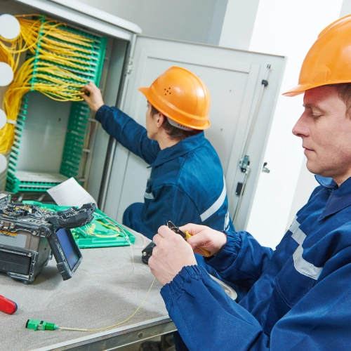
Führen Sie eine proaktive Faserprüfung aus?

Wir helfen Ihnen gern
Wir sind dafür da, Ihnen zu helfen.