DOCSIS 3.1

VIAVI offers performance analysis and troubleshooting solutions to ensure successful installation and maintenance of DOCSIS 3.1® technology. For example, the OneExpert™ CATV handheld tester, cloud-enabled via the innovative StrataSync™ application, offers complete fulfillment and service testing, and affords you end-to-end coverage for your deployments.
What is DOCSIS 3.1?
DOCSIS 3.1 is the current iteration of the telecommunications standard known as Data Over Cable Service Interface Specification, or DOCSIS. This standard regulates the addition of high-speed, high bandwidth data transfer and internet services all internet service to existing coaxial cable lines used in conjunction with a cable modem.
Originally developed by CableLabs in 1998, the standard has gone through multiple revisions and exponential growth in service speed in the ensuing years.

Contractors and technicians working to test or deploy DOCSIS need advanced features enabled on their easy-to-use test set. VIAVI has a great selection of test equipment that supports all service providers, and works to service any DOCSIS 3.1 cable modem or router. Our DOCSIS meters are the fastest on the market and will save you time and money.
While fiber certainly has some inherent advantages over coax cable both in terms of bandwidth and speed, breakthrough technology such as channel bonding has allowed DOCSIS to close the gap with fiber. DOCSIS 3.1 has also differentiated itself in other ways to remain a viable alternative to fiber. Learn more about DOCSIS 3.1 speeds and the advantages DOCSIS 3.1 can offer.
With the development of full duplex, the future of DOCSIS seems assured for years to come. In fact, telecommunications insiders have hinted that DOCSIS 4.0, once completed, could reach cable internet downstream speeds up to 60 Gbps, for a six-fold increase over DOCSIS 3.1, by utilizing up to 6 GHz of the available cable spectrum. With these exciting enhancements in the horizon, the upside of DOCSIS will remain unlimited into the next decade.
The DOCSIS Standard
In 1994, the Institute of Electronic and Electrical Engineering (IEEE) formed a working group of industry experts to develop an international cable modem standard. When the long-awaited specification still had not been delivered more than two years later, cable operators joined forces to form the Multimedia Cable Network System Partners Ltd. (MCNS) and began drafting a new standard of their own. The eventual result was DOCSIS 1.0.
CableLabs began their certification program for DOCSIS equipment in 1998, ensuring interoperability between different vendors’ devices. This has continued through the years over multiple iterations, leading up to DOCSIS 3.1 and 3.1 Full Duplex. The International Telecommunications Union (ITU) has ratified multiple DOCSIS versions as international DOCSIS standards, although discrete annexes of the standards are sometimes required to accommodate differing frequency and bandwidth allocation outside of the United States, such as “EuroDOCSIS”. Certification is often performed by other organizations within the county or region of origin.
DOCSIS Speed Improves
While the proliferation of cable television may have been the driving force that led to a common standard for coaxial cable connections, the eventual result was a remarkably fast mode of internet data transmission that continues to keep pace with the insatiable appetite for bandwidth.
The earliest DOCSIS internet connections achieved speeds surpassing anything that had preceded them, but the innovative premise of internet transmission through coaxial television cable was perhaps ground breaking enough in the early adoption stages. When DOCSIS 1.1. arrived in 1999, the focus was not on enhancing the speed of DOCSIS but improving quality of service (QoS) through privacy improvements and traffic prioritization. Still utilizing a single channel, DOCSIS download speeds clocked in at 40 Mbps, while DOCSIS upload speeds of 10 Mbps were the norm.
Obtaining the improvement in upload speeds that symmetrical applications like peer-to-peer file sharing and VoIP required was a challenging proposition for new millennium developers. DOCSIS 2.0, released in 2002, made use of wider bandwidth to bump DOCSIS upload speeds up to 30 Mbps, but download speeds remained unchanged from DOCSIS 1.1.
The advent of streaming and other data-intensive innovations made additional DOCSIS speed and capacity enhancement imperative. Since replacing or redesigning existing coax lines was not a viable option, more traffic had to be crowded into the same geometric space, all the while traveling exponentially faster. Accomplishing this on our automotive highways would doubtless be a recipe for gridlock or worse. DOCSIS 3.0 was the innovation that rose to this formidable challenge.
DOCSIS 3.0 Max Speeds
There is no doubt fiber has inherent advantages over coax cable when it comes to bandwidth and speed. With an ultra-thin profile, low power consumption over long distances and light-speed delivery, fiber optic cable deployments including fiber-to-the-home (FTTH) have significantly raised the bar for speed and reliability. A cogent improvement was required to prevent DOCSIS from being left behind, and DOCSIS 3.0 delivered this by providing maximum DOCSIS download speeds exceeding 1 Gbps, while DOCSIS 3.0 upload speeds climbed to 200 Mbps or more. The breakthrough technology that made this leap in DOCSIS speeds possible was channel bonding.
“Bonding”, in this context, means sending segments of data simultaneously through multiple channels, then recombining the data at the destination, providing more efficient utilization of the available bandwidth. To the modem, the bonded channels are discrete pieces of one larger channel, even though they are physically separate and not necessarily adjacent. This advancement allowed cable modems to combine multiple quadrature amplitude modulation (QAM) channels into groups, for both the receiving and sending of data.
Each additional channel doubles the data carrying capacity in that direction. For example, what was a 40 Mbps upstream/30 Mbps downstream DOCSIS 2.0 configuration could be multiplied by up to 32x in the downstream and 8x in the upstream using DOCSIS 3.0, producing a maximum total speed of around 1.2 Gbps upstream/240 Mbps downstream.
DOCSIS 3.1 Max Speeds
If high speed internet service was a race, fiber optics would certainly find itself in the pole position. Utilizing new innovations such as wavelength division multiplexing (WDM) and spatial division multiplexing (SDM), transmission speeds over fiber exceeding 9.6 Tbps have been recorded in tests. This is nearly one thousand times greater than DOCSIS 3.1 max speeds. Given the physical limitations of traditional cable, this gap in performance can never be fully bridged. DOCSIS 3.1 has differentiated itself in other important ways to remain viable.
In terms of deployment costs, DOCSIS 3.1 allows the “last mile” between node and subscriber to retain its coax infrastructure, even while the cable feeding these interfaces is increasingly supplanted by fiber. This last mile is where most of the digging, plowing, installing and connecting takes place for pure FTTH installations, so the monetary implications of the DOCSIS 3.1 option are significant.
DOCSIS 3.1 is fully backward compatible with DOCSIS 3.0, meaning users can keep their existing modems rather than making wholesale equipment changes. This backward compatibility has allowed a gradual and seamless transition between DOCSIS iterations. With improvements in error correction also incorporated in DOCSIS 3.1, higher orders of modulation, including 4096 QAM and scaling up to 16384 QAM, are now supported.
- DOCSIS 3.1 Downloads
DOCSIS download speeds have continued to meet the needs of users consistently, and the 10-fold improvement over DOCSIS 3.0 has increased this specification to an impressive 10 Gbps. This has largely been accomplished through the introduction of orthogonal frequency domain multiplexing (OFDM), an advanced modulation technique designed to squeeze even more signals into a finite space by minimizing the space required between them. - DOCSIS 3.1 Upload Speeds
DOCSIS 3.1 upload speeds can reach 2 Gbps. This has enabled seemingly instant transmission of large files, videos, and other content that previously took hours to upload. With new applications like virtual reality and gaming once again driving the demand for symmetric data delivery, Full Duplex DOCSIS 3.1 has been created to provide 10 Gbps speeds for both upload and download directions. This means simultaneous 10 Gbps transmission in both directions, utilizing the same spectrum. - DOCSIS 3.1 Upstream
Given the current focus on upstream performance, it is imperative to take advantage of each opportunity to optimize DOCSIS 3.1 upstream transmission quality. Pre-equalization of cable modem termination system return ports is one way to achieve this. Another important consideration is the upstream modulation profile. By paying attention to the modulation error rate, the actual volume of information contained in the modulated signal can be quantified and optimized.
DOCSIS 3.1 Latency
Since transmission speeds have outpaced most users’ requirements in recent years, noticeable delays in web page uploads, communication responses, and other performance issues are now more latency-dependent than was the case in the early days of DOCSIS. Many web pages require numerous round trips to fully load, so even latency in the 500 millisecond (ms) range can be easily perceptible in the aggregate.
DOCSIS 3.1 technology has improved upon packet-queueing algorithms, leading to a significant improvement in overall packet latency. This is particularly important for applications like online gaming that are more sensitive to perceptible system lag. Active Queue Management has been incorporated into DOSCIS 3.1, whereby the transmission control protocol (TCP) is monitored to optimize traffic flow and buffer levels. Low Latency DOCSIS (LLD) technology can reduce latency to as little as 1 ms.
DOCSIS Provisioning
The benefits of DOCSIS cannot be fully realized unless the correct provisioning steps have been implemented to set up and optimize the network for DOCSIS 3.1. For example, although subscribers may utilize a wide variety of modems and devices, provisioning strategies that integrate firmware management will ensure the latest updates required for optimal performance are intelligently deployed.
Validating DOCSIS configuration files is another provisioning function that is essential for error reduction and efficient device registration. New devices entering an existing provisioning platform should automatically be detected and the DOCSIS version identified. In this way, the correct services can be assigned to the user. Privacy and security are additional QoS concerns that can be addressed through DOCSIS provisioning. Services that scan device leases regularly are one approach that is used to detect and block illegitimate users, preventing unwanted network intrusions.
DOCSIS 3.1 has kept the DOCSIS platform in the high-speed internet conversation through creative physical layer utilization, innovative modulation processes and advanced provisioning protocols. As the five generations of DOCSIS over twenty years have proven, further speed and quality enhancements are always possible. DOCSIS 3.1 speeds have already entered the Terabit zone, but this may very well be only the beginning.
The proliferation of cable TV coincided with the advent of the internet in the mid-1990s. Early internet technology utilized dial-up modems that inconveniently rendered phone lines inoperable while online, while offering speeds of around 56 Kbps. Digital Subscriber Lines (DSL) were an incremental step forward with improved speed and lack of dependence on existing land lines.
Despite the improvements, DSL still relied on twisted-pair phone wire architecture. By the late 1990’s, the potential of our existing coaxial network as the new and logical internet pathway was recognized, and the DOCSIS standard provided a common specification to make cable modems interoperable.
While the original DOCSIS, version 1.0, boasted internet speeds of just 40 Mbps for downstream and 10 Mbps for upstream, this still represented a 10-fold improvement over DSL. The direction for the future became clear. While DOCSIS 2.0 did not improve upon downstream speed, upstream speed increased 3-fold to 30 Mbps. The release of DOCSIS 3.0 in 2006 was another giant leap forward. Channel bonding technology provided the long-awaited boost to downstream speeds, reaching an impressive 1 Gbps, while upstream speeds approached 30 Mbps. Video streaming, social media and increased user adoption continued to push the envelope. To meet this growing demand, DOCSIS 3.1 has taken this fundamental technology to the next level.
The latest iteration, DOCSIS 3.1, has raised the bar once again with downstream speeds up to 10 Gbps and upstream speeds up to 2 Gbps, enabling service providers to offer gigabit internet services to their customers. Speeds in this range had previously only been possible using fiber optic technology, so this breakthrough with DOCSIS 3.1 technology has provided service providers flexibility in maintaining existing coax to home connections without significantly impacting performance.
DOCSIS 3.1 has incorporated multiple advancements to make cable a viable player in the ultra- high- speed arena. Deployment of 3.1 is backward compatible, so customers who delay taking the higher speeds don’t have to upgrade their modem. The improvements engendered by DOCSIS 3.1 merit a closer look at the basic components of DOCSIS, and the opportunities for optimized speed, bandwidth and reliability that have been realized within them.
Physical Layer
The physical layer (PHY), as the name suggests, refers to the visible hardware elements of the system, including the equipment and wiring, as well as the frequencies used for transmission. Utilizing carriers in the range of 25 – 50 kHz wide, thousands of signals can now occupy the same cable that once carried only a few analog television channels. These signals take the form of sub-carriers, disseminating the signal into discrete elements that are later recombined by the receiver, thereby optimizing density and throughput.
OFDM
To put skinny carriers to work, improved technology to minimize or eliminate the guard-banding or spacing between signals was necessary. In DOCSIS 3.1, this has been accomplished through orthogonal frequency division multiplexing (OFDM). This technology takes the existing concept of channel bonding, first seen in DOCSIS 3.0, and builds upon it through the principle of mathematical orthogonality. Essentially, subcarrier signals placed side by side are transmitted orthogonally to one another, thereby enabling the receiver to accurately demodulate the individual signals. This concept is graphically equivalent to the peak of one wave aligning with the low point of an adjacent wave of the same frequency.
Forward Error Correction
Forward error correction (FEC) is a technique through which a receiver can detect errors in redundant signals, then correct them without retransmission. A new feature of DOCSIS 3.1 is a method of FEC known as low density parity check (LDPC). Although FEC existed in past DOCSIS versions as well, improvements in encoding have led to nearly 100% correctable LDPC codeword errors. In turn, this improvement has led to greater noise resiliency and a higher level of modulation.
DOCSIS 3.1 Frequency Range
The DOCSIS 3.1 frequency range has been expanded in stages. This broad overall range is an important element in achieving exceptional upstream and downstream speeds. The current 3.1 frequency range extends from 5 MHz to 1218 MHz, with the upper limit reaching 1794 MHz. The upper frequency limit for DOCSIS 3.0 was a bit lower, at 1002 MHz. Channel bandwidths within the 3.1 spectrum can reach up to 96 MHz for upstream and 192 MHz for downstream.
When DOCSIS 3.0 was released in 2006, the amelioration from DOCSIS 2.0 was both significant and timely. By this time, the quantity of users and requisite bandwidth of applications had each expanded considerably. DOCSIS 3.0 addressed these concerns through significant speed enhancement on both the upstream and downstream, as well as the capability to support IPv6 addresses. The latter was particularly significant with respect to the growing user population, since the volume of addresses supported by IPv4 was reaching its limitations.
Perhaps the most innovative and unique feature of DOCSIS 3.0, now even more fully exploited with DOCSIS 3.1, was the use of channel bonding. This allowed cable modems to combine multiple quadrature amplitude modulation (QAM) channels into groups to both send and receive data. DOCSIS 3.0 technology bonded together multiple 6MHz channels, thereby multiplying speed and bandwidth proportionally.
The enhancement stemming from each new DOCSIS revision is truly remarkable considering the fundamental physical cable has remained unchanged over time. While channel bonding made DOCSIS 3.0 revolutionary, DOCSIS 3.1 has now distinguished itself through the innovative use of OFDM.
Using this concept as a building block, the 6MHz channels have now been replaced by 25 or 50 kHz channels that can be packed even more densely. Improved energy management is another change included with DOCSIS 3.1 that is perhaps a little less well known. A DOCSIS 3.1 cable modem can now utilize a sleep mode, thereby enabling intelligently timed shutoff periods for improved efficiency.
Prior to DOCSIS 3.1, Fiber to the Home (FTTH) was the only available option for consumers seeking the highest order of data transmission speeds. As fiber networks continued to propagate between source and user, the install base of fiber and ultimately the elimination of coaxial cable in favor of fiber seemed like a forgone conclusion. DOCSIS 3.1 has brought continued viability to traditional coaxial connections to the home in an environment where high speed has become requisite.
The overarching architecture for most of these networks is Hybrid Fiber Coax (HFC). This simply means fiber feeding into neighborhoods, with coax cabling continuing to provide the "last mile" between fiber node and user. By contrast, when FTTH is employed, the transitions from coax to fiber are no longer required.
While FTTH installation and DOCSIS 3.1 upgrades each require significant investment, both options provide exceptional performance. The correct balance between fiber and cable will depend on the condition and age of existing coax cabling and the bandwidth requirements of the users, along with the cost considerations. The compact size and versatility of fiber can facilitate the feeding of DOCSIS 3.1 coax networks with maximum efficiency.
DOCSIS 4.0 technology advancements include extended frequency ranges with a high split, and/or full duplex which enables symmetrical data rates. It continues the evolution, boasting symmetric service over cable networks. This means simultaneous 10 Gbps transmission in both the upstream and downstream directions over the same spectrum. In previous DOCSIS releases, the lower part of the spectrum had been dedicated to upstream while the higher portion was dedicated to downstream. The spectrum sharing of full duplex is accomplished through the use of self-interference cancellation and intelligent scheduling.
The boost in upstream capacity is the real breakthrough for full duplex. While DOCSIS 3.1 has done well to keep up with user demands for streaming, gaming and other high bandwidth applications, the next wave of innovation, along with a burgeoning user base, will require upstream capacity in a league with fiber.
Visit Deploying and Maintaining the Advanced HFC Upstream to understand the benefits and challenges with advancements related to the upstream path. A podcast series, “Broadband Lounge” also covers a range of topics related to these advances.
Full Duplex DOCSIS (a part of DOCSIS 4.0 technology) continues the evolution, boasting symmetric service over cable networks. This means simultaneous 10 Gbps transmission in both the upstream and downstream directions over the same spectrum. In previous DOCSIS releases, the lower part of the spectrum had been dedicated to upstream while the higher portion was dedicated to downstream. The spectrum sharing of Full Duplex is accomplished through the use of self-interference cancellation and intelligent scheduling.
The boost in upstream capacity is the real breakthrough for Full Duplex. While DOCSIS 3.1 has done well to keep up with user demands for streaming, gaming and other high bandwidth applications, the next wave of innovation, along with a burgeoning user base, will require upstream capacity in a league with fiber.
With the development of Full Duplex, the future of DOCSIS seems assured for years to come. In fact, telecommunications insiders have hinted that DOCSIS 4.0, once completed, could reach downstream speeds up to 60 Gbps, for a six-fold increase over DOCSIS 3.1. With these exciting enhancements in the horizon, the upside of DOCSIS will remain unlimited into the next decade.
Testing Best Practice
DOCSIS 3.1 increases data capacity up to 50% and speeds up to 10 Gbps on the downstream and 2 Gbps on the upstream—rates that rival fiber.
This section looks at the two main technologies behind DOCSIS 3.1: orthogonal frequency domain multiplexing (OFDM) and low-density parity check (LDPC). It also covers the best testing practices to get DOCSIS 3.1 running at peak performance levels.
Orthogonal Frequency Domain Multiplexing (OFDM)
DOCSIS 3.0 used a single carrier with 6 MHz boundaries (8 MHz in Europe). Modulation is based on single carrier QAM (SC-QAM) and symbols ran through the same carrier in a sequential order. If there was a problem within a carrier, the modulation was reduced to keep data moving—not just for that carrier, but for all carriers in a plant. This means that modulations were optimized for the worst part of a plant.
In contrast, OFDM has boundaries ranging from 24 MHz to 192 MHz. Within these boundaries, OFDM can run as many as 8000 subcarriers running at 25 kHz or 50 kHz over the entire bandwidth. All subcarriers are time synchronized across the bandwidth and communicate together to form symbols. These symbols carry codewords and are spread across multiple subcarriers and time slots.
The main takeaway is that symbols are no longer tied to specific frequencies, but instead, are allocated across different frequencies over the entire bandwidth. This creates some unique opportunities. Now, if a particular subcarrier is experiencing a problem, OFDM can simply exclude it by bridging the adjacent subcarriers together. This allows symbols to continue to travel over the entire bandwidth at optimal performance levels.
Since OFDM is modulated for a set period, the technology can shape subcarriers by controlling their phase relationship. If one subcarrier has a peak, the adjacent subcarrier can be shaped to have a null. This reduces interference and provides an opportunity for higher modulations.

Modulations are where OFDM makes significant improvements in network performance. Instead of using one modulation for the entire plant, OFDM can allow different modulations for each subcarrier. Profiles can be created that define what modulation is used on each subcarrier and multiple profiles can be created for this purpose.
As an example, look at one subcarrier. Each profile has its own modulation (for example, 64 QAM, 1024 QAM, 2048 QAM, or 4096 QAM). OFDM can use the profile that has the highest QAM that a subcarrier can handle for each portion of the HFC plant. In one part of the plant, that might be 4096 QAM. In another part, it might be 1024 QAM. There could be too much interference in the next, and so that spectrum is excluded in the specific profile. In the next piece of spectrum, the interference is gone and a profile with 2048 QAM is used. OFDM can do this using variable bit loading of the profiles.
Now, expand what is happening on this one subcarrier to cover all 8000 subcarriers. Each profile controls every subcarrier to maximize the performance on a particular subcarrier at a specific moment in time.
As mentioned before, all subcarriers are linked with each other to form symbols and those symbols carry codewords. The subcarriers are allocated to codewords on each symbol and their modulation is controlled by a profile. Each profile is assigned a letter (for example, A, B, C, and D). Not only is each subcarrier optimized for performance, all the other 8000 subcarriers know what each subcarrier is doing.

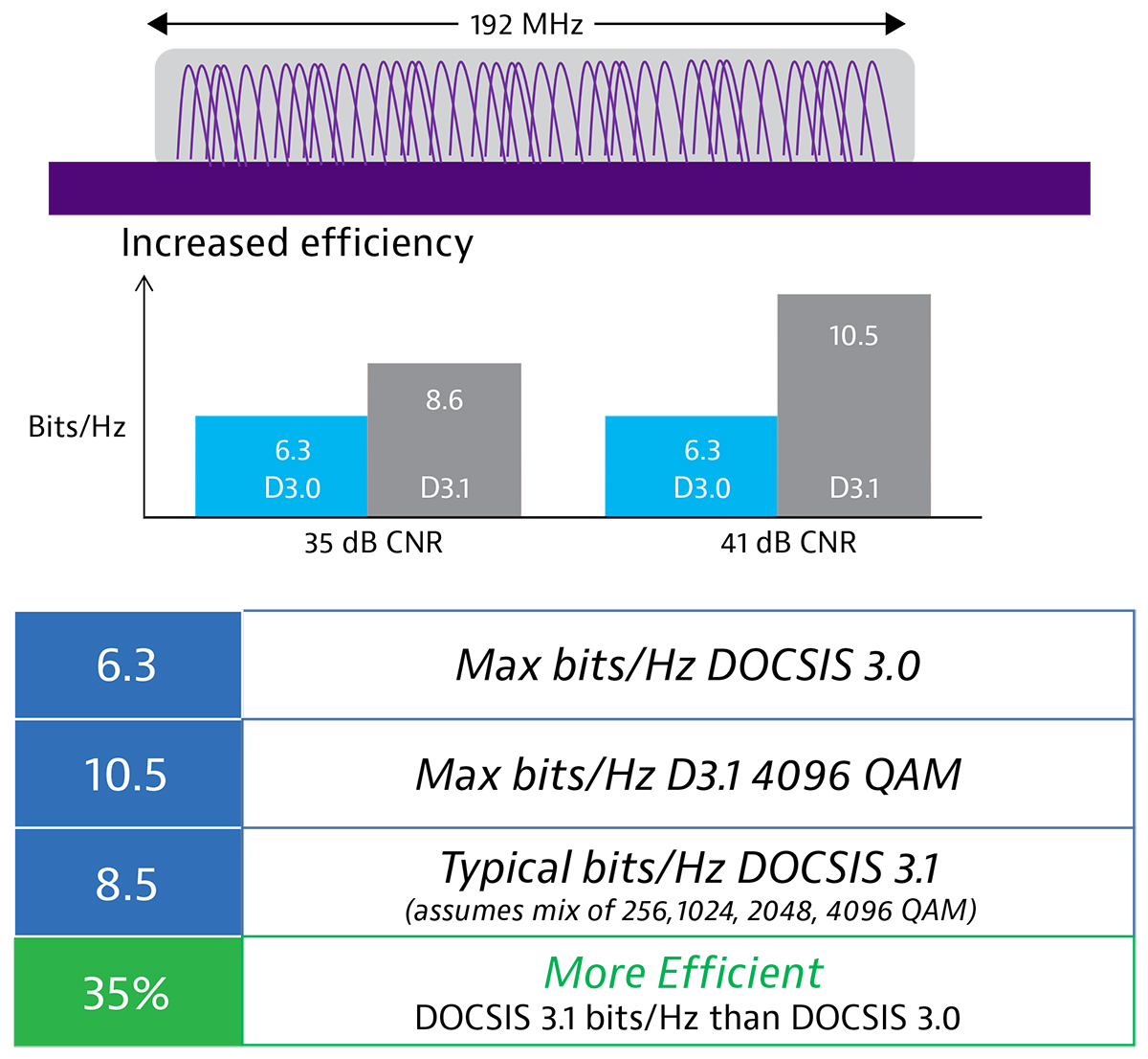
Instead of modulations being optimized for the worst part of the plant, they can now be optimized for the best part of the plant at any given moment. This makes DOCSIS 3.1 much more efficient than its predecessor. Where DOCSIS 3.0 was able to achieve 6.3 max bits/Hz, DOCSIS 3.1 can achieve 10.5 max bit/Hz at 4096 QAM. In a more typical situation where multiple QAMs are being used at the same time, DOCSIS 3.1 is still able to achieve 8.5 bits/Hz—making it 35% more efficient without changing the HFC plant.
Low Density Parity Check (LDPC)
The advances made by OFDM would not be possible without some form of error correction. DOCSIS 3.0 used Reed-Solomon forward error correction and measured bit errors as a ratio (BER). BER is relevant on single carrier systems, but OFDM no longer uses single carriers. Since OFDM spreads the data across multiple subcarriers and potentially different subcarriers on every symbol, BER no longer makes sense.
DOCSIS 3.1 uses LDPC instead. LDPC can see across the entire bandwidth and looks for codeword errors instead of bit errors. If codeword errors are correctable, LDPC will automatically adjust correct the codeword so that higher modulations can be obtained. This greatly reduces the need for retries and keeps subcarriers working at optimal levels. LDPC is designed to allow data to be transmitted at its theoretical limits.
But LDPC does have one downside. As LDPC makes real-time adjustments, it can reach its limits regarding power levels and modulation error ratio (MER) while trying to correct codewords. This means that LDPC gives less warning of impending failure. If LDPC goes over this edge, codewords can become uncorrectable and customer quality of experience (QoE) begins to decline. To keep this from happening, testing becomes even more important.
Testing for Peak Performance
For accurate testing to happen, it is important to understand the building blocks that make up OFDM. At the base is the PHY link channel (PLC) that contains information on how to decode the OFDM signal. Without the PLC, the modem cannot find the OFDM carrier or understand how to decode it. One level up is the next codeword pointer (NCP) that tells the modem which codewords are present and which profile to use on each codeword. Next is profile A. This is the boot profile that every DOCSIS 3.1 modem must be able to use to reach higher QAMs with the other profiles.
Beyond profile A is where power levels, MER, and noise levels are tested for OFDM. Once this is complete, profiles B and above can be used to reach higher QAMs and more efficiency. Profiles beyond A, B, C, and D are up to the discretion of the CMTS and CM manufacturers but there are no limits to the number of profiles that can be used.
When testing the PLC, it is important that it is locked and that there are no uncorrectable codeword errors (CWE). The PLC must be robust, so the power level and MER must be well within range so that it can be decoded. The DOCSIS 3.1 standard limits the PLC to use BPSK or 16 QAM.
Once the PLC is running properly, the NCP must also be locked and have no uncorrectable CWE. If there are lost messages at this point, there will be retries, or even worse, no communications at all. The DOCSIS 3.1 standard allows the NCP to use QPSK at 16 QAM or 64 QAM.
Since profile A is the boot profile, it can be assigned lower mixed QAMs such as 64 or 16 so that all DOCSIS
3.1 modems can communicate in the worst part of the plant. These lower modulation rates can operate at lower MER and power levels. Just like the two building blocks before it, profile A must be locked and have no uncorrectable CWE. If there are uncorrectable CWE, the modem will resort back to DOCSIS 3.0 and all efficiencies will be lost. Profile A can run at higher modulations but will start to experience correctable CWE. This is okay if they do not become uncorrectable CWE.

Now that these three building blocks are working within proper levels, it’s time to look at the overall performance of an OFDM carrier. One mistake technicians can make is to test the power level across the entire 192 MHz carrier. Keep in mind that the total power of an OFDM carrier is equal to the total power of a 6 MHz carrier plus the channel bandwidth. Because of this, the total power of an OFDM carrier is greatly different than that of a single 6 MHz carrier. To make accurate power level adjustments, the power levels must be measured and referenced in comparison to the power in a 6 MHz carrier.
There are also a few unique characteristics to OFDM. The first and last 6 MHz of an OFDM carrier will be approximately 0.8 dB less than the other carriers due to roll-off in the guard band. This becomes important when using a standard meter or when looking at the power within individual 6 MHz blocks of OFDM. In addition, the PLC carrier will be approximately 0.8 dB higher than the other carriers due to the additional pilots and data patterns. Lastly, the overall flatness related to a 6 MHZ carrier in OFDM will show a 1.6 dB variance due to the low- and high-end roll-off and PLC variations.
For OFDM to operate at peak performance, the average power level must be within range, MER must be good, and noise levels must be as low as possible. Noise greatly affects OFDM and can prohibit the use of higher-profile modulations.
Once OFDM is performing well, higher profiles become possible. With each profile, it is important that they are locked. The higher profiles can have acceptable amounts of uncorrectable CWE since it is not as critical as it is in the lower building blocks, but uncorrectable CWE can restrict higher profiles from performing at their peak.
For example, if profile C has some uncorrectable errors, profiles D and above will not be able to go beyond the modulation being used by profile C. For the higher modulations to occur, the HFC plant must be clean to prevent uncorrectable CWE

DOCSIS 3.1 Peak Performance
DOCSIS 3.1 solves a major dilemma that providers have faced for years: “Do we spend money to completely upgrade the plant or make do with incremental improvements to our existing plant?” With OFDM and LDPC in place, providers can make significant performance improvements with few upgrades to the plant.
Very little needs to be done to the physical plant to gain 35% more efficiency out of a network, giving providers enhanced speed and throughput immediately. This also gives providers more time to make incremental improvements to a plant that can push DOCSIS 3.1 to even higher levels of performance.
However, providers must be careful in the way they deploy and test DOCSIS 3.1. The best practices laid out in this paper will ensure that DOCSIS 3.1 is working at peak performance, reducing the number of truck rolls by technicians, and providing a higher level of QoE for customers.
Learn more about DOCSIS 3.1 from VIAVI today!
Are you ready to take the next step with one of our DOCSIS 3.1 test products or solutions? Complete one of the following forms to get going:

Optimizing DOCSIS 3.1 Performance

Perspective on DOCSIS 3.1
Ресурсы
White Papers и книги
Products
News
-
Hаграда--Английский
BTR Awards VIAVI with 4 Diamonds: NoiseTrak
-
Hаграда--Английский
BTR Awards VIAVI with 4 Diamonds: Network and Service Companion (NSC-200)
-
Hаграда--Английский
VIAVI Solutions breaks record in the 2021 BTR Diamond Technology Reviews
-
Пресс-релизы- -Английский
VIAVI Introduces Industry’s First DOCSIS 3.1 Installation and Service Solution to Accelerate Deployment of Gigabit to the Home
-
Компания в новостях--Английский
VIAVI Takes DOCSIS 3.1 to The Test