Submarine Cable Networks
State-of-the-art solutions for submarine cable networks

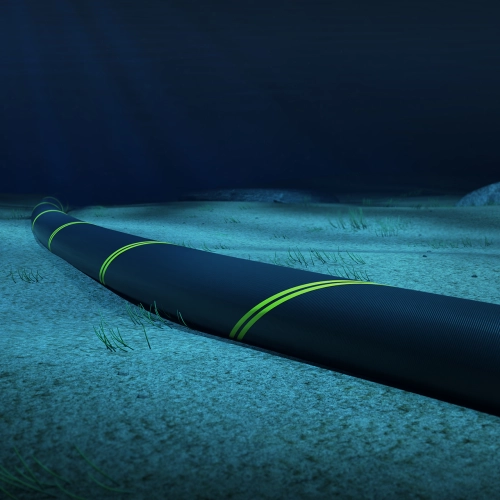
A submarine cable is a communications cable laid on or below the floor of the ocean or other body of water. A submarine cable network is an integrated system of cables collectively providing data transfer from one land-based location to another. This network includes the cable itself as well as other hardware components and infrastructure that make this large-scale communication possible. Despite the proliferation of satellite communications, over 95% of international data transfer is still performed via submarine cable networks.
These cables vary in size depending on the number of fibers in the central core, the marine environment (sand or rock), and the depth of water. They are specially constructed to protect the physical layer fibers carrying data from moisture and damage. The optical fibers in the inner layer of a cable are held inside a small plastic/nylon tube filled with a protective/lubricating gel, this tube is typically surrounded by multiple galvanized steel strands and encased in copper or aluminum tubing. This tubing is then further protected with a layer of polycarbonate, another aluminum water barrier, stranded steel wire for weight and mechanical strength, and then outside layers of mylar and polyethylene for additional waterproofing. There are many variations of cable construction which depend on the network's architecture, planned usage, deployment depth and environment, etc.
Submarine Cable Test Tools
Building, activating, and maintaining submarine cable networks present unique challenges associated with accessibility, long distances, and constant exposure to the elements. Throughout the network life cycle, it is critical to use the right test and monitoring tools. See all submarine cable test tools.
Construction
During construction, end face inspection can detect dirt particles or other physical defects whose impact can either diminish or halt the performance of the network (and produce bad test results). Perhaps the most essential tool for physical layer fiber verification is the OTDR. Specialized types can be used for long haul wet plant OTDR as well as versatile bidirectional dry plant OTDR.

Another parameter that must be measured and controlled during cable deployment for submarine network construction is the amount of strain being placed on the actual fibers; this must be lower than 0.34% for submarine fiber grade (IEC 60794-3-20), higher values will reduce the lifespan of the fibers. Strain measurement can be performed using portable Brillouin OTDR. Optical dispersion tools are also pivotal to the characterization of networks in order to baseline optical dispersion and assess if any dispersion compensation is required.
Activation
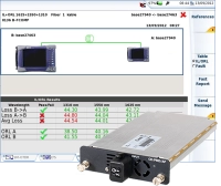
Service activation requires tools for optical power measurement and spectrum analysis along with data network equipment testing. In order to quantify optical power, a ruggedized optical power meter is an essential tool. High quality Optical Spectrum Analyzers (OSA) for performing Optical Signal-to-Noise Ratio (OSNR) measurement and Network testers for latency, throughput, jitter, and frame loss/bit error rate analysis are also a must during this phase to validate and certify network performance.
Monitoring & Maintenance
Monitoring and maintenance are the keys to keeping the vital cable networks performing optimally. To assess the fiber's physical health, an effective optical network monitoring system such as ONMSi can provide real-time fault, degradation, and security issue monitoring.
Fiber monitoring of links is an essential ongoing function. ONMSi can be used to detect fiber degradation and a wide array of fiber monitoring techniques may be utilized to meet the unique challenges associated with a fault. For example, to detect fluctuations in strain, temperature, and other parameters inherent to submarine cables, fiber optic sensing tools play a critical role. In addition, service performance monitoring is key to proactively identifying data issues (such as latency, throughput, jitter, and frame loss/bit error rate) and is usually required in order to prove SLA compliance for customers.

ONMSi

Service performance monitoring
Submarine Network Architecture
The overall architecture of submarine cable systems is probably best defined by the individual elements it is composed of from end to end. Each of these components plays an essential role in maintaining the integrity of data through thousands of miles of unpredictable ocean.
The wet plant is a term used to describe all the network elements that reside underwater. The boundaries for this wet plant are the two beach manholes where the cable either enters or exits the water. Discrete parts of the wet plant include the cable, equalizers, branching units, and submarine repeaters.
Conversely, the dry plant, as it is known, consists of the subsea cable network segment on land between the beach manhole and the cable landing station. This includes power feeding equipment (PFE), submarine line terminals, and land cable segments.
The subsea cable system is connected to the terrestrial network at the landing station, with the backhaul system providing a connection to the dry plant. The landing station is where the head end and data center is found. These landing sites are usually located in areas with low levels of marine traffic, mild currents, and gently sloping sea floors so that the wet plant cables can be more easily buried/landed for linking to the dry plant.
As the name suggests, umbilical cables provide a lifeline between the seafloor and a land-based position. This type of ocean cable may be used to supply power to a subsea cable network from a ground position or floating position along with the cables in the ocean run.
Over one million kilometers (km) of submarine ocean cables currently transverse the world's oceans. A submarine cable map accurately represents the placement of all submarine cables.
The range of optical signals is limited due to attenuation. One way to overcome this is through the use of repeaters at discrete intervals over the cable run. For subsea networks, the repeaters are powered in series by the power feeding equipment (PFE) of the dry plant. To maintain the correct optical power levels and ensure adequate Optical Signal-to-Noise Ratio (OSNR) for data signals that electrically powered optical amplifiers that can be used to repeat those signals. Most of the amplifiers utilized in submarine links are Erbium-Doped Fiber Amplifiers (EDFA) which have inherently low noise and high (> 15 dBm) output power.
Design choices made for these networks typically relate to whether repeaters will be used, and if so, how many. Another design consideration is whether or not the cable runs will branch in multiple directions or simply travel from point to point. Unrepeated cable systems have the inherent drawback of limited range, with 400km being the approximate limit. On the other hand, these unrepeated systems can be cheaper to deploy and maintain due to their lower complexity as there are no repeaters required and hence no powering.
Subsea Cable Testing – What to Measure and Certify
The complexity of these networks makes it extremely important to test and certify all segments of the wet plant, dry plant, and landing station, including the interfaces between these elements. For the wet plant, OTDR testing is vital to measure attenuation across the entire length of the cable.
For repeated systems, this includes measurement through the in-line amplifiers. For non-repeated systems, long-range OTDR may be required. Other testing required to certify the wet plant includes chromatic dispersion (CD) and polarization mode dispersion (PMD).
The dry plant must also be tested and certified, including verification of error-free data transmission to the wet plant. The integrity of SLTE patching and the manhole splice should be verified. Optical Spectrum Analysis (OSA) through the dry plant connection is another critical test point. The data networking elements of the landing station must also be vetted, along with the fiber backhaul. As with a purely land-based network, latency, throughput, jitter, and frame loss are potential test metrics to assess performance. The time associated with protection switch service disruptions should also be evaluated.
Learn More About Submarine Cable Networks:
With so much worldwide data now traveling through these networks, their importance to global communication, commerce, and security cannot be overstated. This can be traced to the earliest history of these networks when British domination of this industry engendered military, commercial, and political advantages.
Suppose your customer-facing website is slow because of poor network performance. Potential customers lose patience with the site and decide not to buy your products or services. Or, perhaps you're looking to move into a different market. If your network can't handle the demands, such a shift would place on it, your efforts will be in vain.
Submarine cable ownership today by individual governments has given way to consortiums of multiple telecom carriers who build, monitor, and maintain these huge networks. In recent years, many Internet Content Providers (ICP) and data center owner and operators have also entered the fray of submarine cable ownership to ensure their own interests in this valued commodity.
The range of uses for undersea cable knows no boundaries. With international internet and phone communication relying so heavily on these networks, almost any business, government, or individual who owns a computer is a daily user. To meet this growing demand, submarine internet cable bandwidth continues to increase. For example, the 6600 km MAREA cable from Virginia to Spain is capable of carrying 160 terabits per second (Tbps) of data.
In 1850, the first undersea telegraph cable was built between England and France. Since modern insulating materials did not yet exist, substances like India rubber and Gutta-percha were used to protect the copper wires, often unsuccessfully. Most early networks were owned by the British and the available science of that era severely limited bandwidth.
Telephone repeater technology evolved sufficiently by the 1950's to make the first transatlantic submarine phone cables possible. The popularity and widespread adoption of these services spawned additional amplifier and repeater development to increase the efficacy of these early networks.
Originating in the 1980s, internet cabling has supplanted the legacy coaxial submarine phone cable networks with TAT-8, the first submarine optic cable laid across the Atlantic ocean. It was installed in 1988. Optical amplifiers, materials, and multiplexing capabilities have continued to evolve since that time making today's submarine cable networks the preferred option for worldwide communications.
Despite these advancements in construction and actual submarine network build and deployment, they are still vulnerable. The ever-present hazards presented by fishing equipment, anchors, and shifting currents have continued from the first submarine networks through the present day and can diminish the data capacity of a submarine network or even render it inoperative altogether.
Submarine cabling is not a new concept. In fact, it was first implemented in 1858, connecting Newfoundland and Ireland through a telegraph cable that was placed deep beneath the sea's surface. While this was revolutionary at the time, the first non-test message that was sent was a 509-letter message that took 17 hours and 40 minutes to be delivered across the Atlantic ocean. However, since those times, the technology and techniques used have drastically changed (and improved) for the better.
What are Submarine Cables?
A submarine cable is a communications cable that is laid beneath the ocean's surface that provides data transfer from one land-based location to another. Varying in size, the cables are equipped to withhold any environmental elements which may be present within the sea, as well as the depth of water in which they are situated.
Historically, submarine cables took approximately four years to install, lasting only one month before breaking down due to the harsh conditions. First constructed from a telegraph line, submarine cables have progressed to telephone and coaxial lines, with all modern submarine cabling using fiber optics.
Today, fiber-optic technology uses lasers that send rapid waves down through thin glass fibers (optical fibers) to the other end of the cable. The filaments (fibers) are protected by layers of insulation as they are as thin as a strand of human hair. The cables that are laid within shallow water are much stronger and thicker than those located deeper within the ocean as they have to withhold tougher conditions.

Future of Submarine Cabling
There are three main ways to transmit data signals across large spans of land (phone cable, coaxial cable, and fiber optic cables) which either send data through the air or through the sea. With 99% of internet data sourced from submarine cables and more than 380 active cables lying on the bottom of the ocean, the need for submarine cables is evident.

The demand for internet and cloud computing is expanding and the need for faster, more reliable service is here. In fact, the demand for global bandwidth is growing at up to 40% each year, with analysts predicting the installation of fiber optic cables to hit the 2 million kilometer range in 2020. It is expected that 53.7% of the world's population will have access to the Internet by 2021 which equates to an estimated 4.3 billion people. The submarine network is the most reliable and cost-effective solution in keeping up with such demand with submarine internet cable bandwidth continually increasing. As such, the 6600km MAREA cable, which spans between Virginia and Spain, is equipped to carry 160 terabits of data per second.
While submarine cabling is a slow and expensive project, it is still the cheaper and faster alternative to satellites. Although both options are still susceptible to vulnerability and damage, it is far less likely for subsea cables to suffer from threatening damage. A single cable can carry tens of terabytes of information per second where satellites fall short, being able to only carry approximately one terabyte per second. With new phase modulation techniques and the latest advancements in submarine equipment, the capacity has increased to 8000%, ensuring that submarine networks are well prepared for the heightened demand of data and internet traffic.
The range of VIAVI testing and monitoring tools are designed specifically to handle all aspects of the submarine cable network and subsea cable services, from the building stage right through to activation and monitoring. The submarine network typically poses unique obstacles due to the environment and conditions that the cables are situated within which is why it is critical to be equipped with the right instruments. As such, the entire architecture of a typical submarine cable network is divided into elements (wet plant, dry plant, landing station, umbilical cables, lengths/distances, and repeaters/amplifiers). Each element plays a crucial role in protecting and delivering the data throughout the network system. Protect and monitor the submarine network with end-to-end solutions from VIAVI.
Reliance on global high-speed telecommunications is higher than ever before. From urgent financial transactions to endless video live-streaming, undersea cables support numerous aspects of our modern lifestyle that we may not be aware of, making it one of the backbones of the global economy. In fact, commercial undersea cables carry about 97% of the world's internet and telecommunications data, according to a 2019 report by StableSeas.
As of 2020, there are over 1.2 million kilometers of submarine cables in service globally, TeleGeography reported. These cables carry over $10 trillion of financial transactions, as well as massive amounts of web data and internet traffic across the world at the incredible speed of millions of miles per hour. Various sectors, including the international banking industry, commercial trade, defense data, and daily internet usage, relies on this critical infrastructure. Concerningly, the integrity of this vital global communication is significantly at risk from accidental and deliberate damages.
As 5G and other technologies transform our societies into highly integrated networks, protecting our digital infrastructure - such as undersea fiber-optic cables - becomes more important than ever. Let's dive deeper to understand the challenges facing submarine fiber-optic cables and how to overcome them.
Accident-Prone Environment
Submarine cables are engineered to sustain around 25-years of shelf life. However they are often retired earlier than that when they start to become economically obsolete. Over that long period of time, the environment takes its toll on the cable. Shifting tides, erosions, storms, and saltwater intrusion are all potential disruptors of data flow. As a matter of fact, around 6% of cables are damaged through abrasion as the current scrapes cables against rocky surfaces. These damages coming from the environment often cause a variety of issues, starting from minor outages and lowered speeds to a full loss of connectivity.
Anchor Dragging and Fishing Activity
Not surprisingly, the larger and more significant physical threats are man-made, coming from accidents due to fishing vessels and dragged anchors. This type of accidental damage make-up about 60% or two-thirds of all submarine cable faults, TeleGeography reported. This accident occurs when fishing boats and large ships are dragging their anchors outside the designated anchoring areas, thus hitting subsea cables. Recent fault records have indicated that merchant ships sometimes forget to fasten their anchors securely when traveling during short passages.
Threats from Shark Bites
Cable faults due to shark bites are exceedingly rare, and it is perhaps the biggest myth cited in the press. While it is true that in the past, some curious fish and sharks have bitten a few cables and caused damage, in general, they are not a major threat. Both barracuda and sharks have been found to cause cable failure in the past, as reported by the 2009 UN Environmental Program report. Their bites tend to penetrate the cable insulation, thus allowing seawater to compromise the power conductor.
Damages by Extreme Seismic & Weather Events
Natural disasters - such as mudslides, typhoons, tsunamis, and earthquakes - are also major threats to undersea fiber. In Asia's underwater network, a large number of cables is concentrated in the middle of a major seismic belt, which resulted in many catastrophes in the past where natural disasters severed about half of the pre-existing trans-pacific cables. Quake-damaged undersea cables are, unfortunately, quite common, especially in earthquake-prone countries like Japan and Taiwan. When submarine cables are severed following a major earthquake or other natural disaster, it can cause disruptions in internet access and communications traffic that could cost both money and time.
The Solution
To overcome damages to undersea cables, the subsea networks developed over the past five years were designed with enhanced physical security in mind. In order to protect the fiber-optic cable from water environmental hazards, the undersea cables are typically wrapped in multiple layers of protective coating. To further increase its protective property, the cable is encased in a protective pipe that extends for several miles from the shoreline. In some cases, operators may use automated technologies that are placed inside the cable housing's repeaters. This technique can help to avoid the cost and time of pulling the damaged cable out of the sea to fix it, only to redeploy it underwater.
To deal with extreme seismic and weather events, the Southeast Asia-Japan Cable (SJC) consortium designed an underwater fiber cable deployment path that intentionally avoids the earthquake-prone zone in North Asia. Similarly, the route of NTT Communications Corporation's (Tokyo) Asian Submarine-cable Express (ASE) has taken a similar approach. Their new line is designed to go around the damage zone, rather than taking the shortest, straightest line from both ends. This model is intended to bypass high-risk zones and avoid the damage caused by both earthquakes and typhoons.
Final Thoughts
Ultimately, undersea cables help keep the global economy well-functioning and connect people around the world. Protecting these critical infrastructures from any compromise is a vital national interest of a country. One way of doing so is by performing regular repairs and maintenance through submarine cable services. Doing so will ensure the cables' integrity is not being threatened by any disruptive damages. Risk-mitigation steps can be done by using a monitoring system to supervise the fiber-optic network in real-time and sound alerts when problems arise.
Considering the importance of protecting and monitoring undersea fiber optic cables, it is essential for telecommunication companies to continue their effort in overcoming the challenges of submarine cable maintenance.
Submarine Cable Network Products
Reference Guide to Fiber Optic Testing
Reference Guide to Fiber Optic Testing: Volume 2
Test your Submarine Cable Network with VIAVI today!
Are you ready to take the next step with one of our submarine network products or solutions? Complete one of the following forms to continue:
Позвольте вам помочь
Мы всегда готовы оказать вам всю необходимую помощь.