What is Signal Leakage?
Learn about the challenges of signal leakage testing and the importance of monitoring and controlling leakage for improved customer experience and minimized service disruptions.
What is RF leakage? Signal leakage refers to the loss or egress of radio frequency (RF) signals from a cable system when they are not properly contained. This can result from a multitude of causes but is generally the result of shielding defects within the cable network. In the US, FCC standards for signal leakage encompass egress from both analog and digital cable systems. Signal leakage has taken on renewed importance recently as issues like LTE interference have piqued government and mobile operator attention globally.
Why Signal Leakage Monitoring is Important
In theory cable networks are closed systems completely isolated from any off-air signals which may be present. This concept allows frequency sharing between off-air and cable signals such as AM/FM radio, remote control cars, wireless phones, CB radio, aeronautical communications, cell phones, and many others.
The reality is that cable networks are not perfectly sealed, and as a result signals from cable networks can escape (egress) and interfere with off-air signals at the same frequencies. Conversely, off-air signals can enter into the cable network (ingress) and interfere with the cable signals.
The FCC limits imposed on signal leakage originated from a public safety perspective, with leakage monitoring in the 108-137 MHz aeronautical band being performed since the 1970’s. RF signals are essential to modern air traffic control systems, so interference caused by leakage beyond an acceptable threshold must be controlled.
With today’s widespread propagation of wireless communication, this same type of egress from cable plants can also disrupt Long Term Evolution (LTE) data transport at higher (UHF) frequencies. Mobile operators pay very high license fees for exclusive use of spectrum bands in this range to deliver cellular services to their customers, and in the US the FCC has the authority to fine any entity which generates interfering signals in these licensed spectrum bands. Similarly, ingress originating from off-air LTE signals has the potential to disrupt wired cable networks if HFC shielding is compromised. In this way, adherence to standards originally intended to enhance public safety can provide the additional benefits of improved customer experience and minimized service disruptions.
Aside from potential for interfering with off-air signals, leaks from cable plants are an indicator of shielding weaknesses that can manifest in many other ways and impact cable subscriber quality of experience. While HFC leakage detection and remediation systems were originally adopted to comply with US FCC requirements, cable operators globally have recognized the value in overall plant hardening enabled by finding and fixing plant weaknesses identified by leakage tools.
Check out the new standard in GPS leakage management
The challenges associated with signal leakage might be best summarized through an analogy to fluid leakage, since damaged connections, aging parts, and open-ended lines are some of the potential leakage sources in both instances. However, unlike fluid leakage, cable signal leakage is invisible, and therefore more difficult to pinpoint the source of the leak. Given this constraint, a signal leak from one location can potentially mask a leak from a nearby location. Signal leaks can also be intermittent, meaning a slight bend or movement in the cable from one point in time to the next can render the leak undetectable. Metal objects can also interfere with signal leakage detection equipment.
Since this equipment was originally conceived to accommodate the aeronautical VHF frequencies, long standing practices and equipment are not always effective in detecting leakage at higher frequencies or measuring noise-like QAM signals. Rapidly changing technology and increased airwave traffic requires versatile test equipment, technician training, and processes to evolve at breakneck speed.
Another challenge facing leakage monitoring systems is determining which detected signals originate from within a specific cable network versus from other sources. To allow this discrimination, leakage monitoring systems will inject a “tag” or unique RF signal into the cable plant that can then be detected by the field monitoring tools. Anytime that the field gear detects this unique tag signal they can be sure that the detected signal is leaking from their specific system and not an overbuilt competitors’ system or other ambient source.
Instead of detecting signal tags injected into downstream or OFDM pilot leakage out of cable networks, an innovative approach has been developed for use in high split plants. This approach uses OFDMA Upstream Data Profile (OUDP) test bursts transmitted by DOCSIS 3.1 or higher cable modems as the unique signal that advanced leakage detectors use to identify emissions from HFC networks. These test bursts are already defined in DOCSIS specifications, all deployed DOCSIS 3.1 CPE should support OUDP operation with no new development required. Many legacy leakage meters deployed today don’t have hardware capable of OUDP detection, but advanced meters with software-defined radio-based architectures like the VIAVI Seeker X can with just a field-deployable firmware update.
While the equipment and technology has changed radically since egress testing was first implemented for use in the aeronautical band, the basic tenants required for accurate signal leakage testing remain unchanged. Calibration of all leakage detection equipment is the first important step for ensuring accurate measurements in the field or subscriber premises.
Routine Monitoring
The FCC mandates all cable operators to routinely identify and repair any cable leakage measured to be greater than 17 µV/m at 3 meters and maintain leakage maintenance records. In addition, the cumulative leakage index (CLI) must be assessed once per year.
Established in 1985 to protect the integrity of aeronautical communications, the CLI is a measure of the cumulative or additive signal leakage produced by the system in total. This index can be determined either through ground-based testing (drive out through system and log all leaks), or by using specialized aircraft to measure the leakage from an altitude of 450 meters.
Outside plant leakage testing is generally performed by driving in a methodical pattern, using GPS to locate leakage locations on a map. When leaks greater than 17 µV/m are detected by leakage meters, FCC guidelines for leakage measurement and repair must be followed. Ideally the same gear that is used in drive out testing can be removed from the truck and used for walk out testing to find and fix the actual leak sources. It is critical that leakage gear support both low and high frequency leaks as most leaks are frequency-specific and show up at just one end of the spectrum or the other. Much of the magic in leakage monitoring systems resides in the centralized post-processing of field leakage data to eliminate redundant leaks and properly indicate the lat/long coordinates of the leak source.
Although the monitoring of outside cable leakage is required by the FCC, the practice should be considered a prudent one for maintaining safe and effective operations, regardless of the regulated requirements. Monitoring “drive out” leakage can also supplement user leakage data trending and paint a more complete picture of the overall system leakage. Ideally, leakage drive out data is correlated with proactive network maintenance (PNM) data to pinpoint the location of plant issues, quantify number of subscribers impacted by them, and speed the field find and fix process.
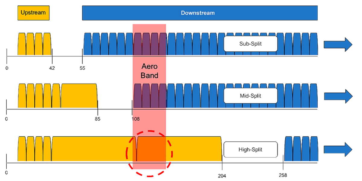
Cable operators globally are beginning to implement high-split architectures, extending their upstream frequencies from 42 or 65MHz up to 204Mhz in an effort to keep up with exploding broadband upstream demand. Expanding a 42MHz network to 204MHz in the upstream provides >500% increase in usable spectrum, potentially deferring the need for node splits for many years. This migration creates many challenges, with high-split leakage being among the toughest. The aeronautical band that is subject to the FCC mandate currently resides in the downstream of sub-split and mid-split networks, but moves to the upstream in high split networks. This breaks existing leakage processes and equipment and drives the need for a new approach.
Home Signal Leakage Testing
Signal leakage detection inside the end user’s premises using the same techniques as plant leakage requires high sensitivity equipment because the signal levels within the home are lower than outside plant levels, especially when digital services are installed. The lower signal levels within a customer’s home also make it less likely for these leaks to interfere with off-air signals outside of the home but testing for leakage in the home is critical for another reason. As mentioned earlier, the same shielding weaknesses that allow egress out of the cable plant also can allow ingress in. Up to 95% of ingress into cable plans comes from homes and drops, so ensuring that homes/drops are tight can pay huge dividends for cable operators in improved service quality and reduced OPEX.
Pressure Test with HL Transmitter
Leakage meters that can detect potential egress/ingress points even when the ambient source is not present are vital to maintaining a high-quality user experience. Going back to the fluid leakage analogy, a common technique used to test for existing or potential fluid leaks is the use of hydraulic pressure to detect or verify resistance to leakage. The increased pressure enables detection of minor weaknesses that would be undetectable at standard pressures.
This same basic concept can be employed for in-home signal leakage testing. By utilizing the Seeker HL in conjunction with an OneExpert (ONX) or DSP meter, high output test carriers at +60 dBmV can be injected into the system at the ground block or tap, thereby “pressurizing” the home network to make weaknesses due to damage or other quality issues more easily detectable.
OneCheck Test on OneExpert
Automation and simplification of test practices is extremely valuable as it can lead to more efficient and consistent in-home leakage certification and troubleshooting. The OneExpert (ONX) CATV signal analysis meter features a OneCheck dashboard with a collection of stored automated tests. Pressure testing routines are a natural fit for this recall interface.
Get Introduced to Home Leakage Testing with VIAVI
Start detecting signal leakage with VIAVI today!
Are you ready to take the next step with one of our signal leakage products or solutions? Complete one of the following forms to continue: