Essential Fiber Optic Testers
Fiber Optic Test Tools for all Networks

Experience fiber testers that achieve industry standards and promote ease-of-use.
Products
-
")
INX 700 Probe Microscope
Automated single and multifiber connector inspection and the industry’s first AI-enhanced image analysis
-

INX 660 Probe Microscope
Automated single fiber connector inspection and analysis
-
")
OneExpert HFC (ONX 720/730)
Comprehensive DOCSIS, PON, Ethernet, and WiFi 7 testing made easy through integrated automation.
-
")
OneExpert Fiber (ONX-700)
Comprehensive PON, Ethernet, and WiFi 7 testing made easy.
-

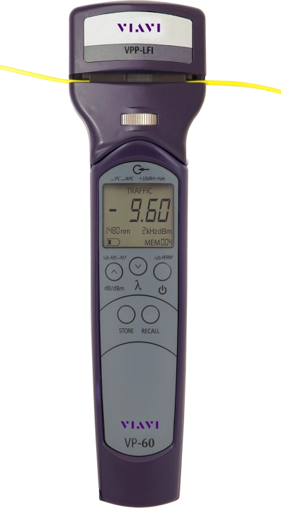
FI-60 Live Fiber Identifier
Live Fiber Identifier easily identifies the optical signal without having to disconnect the fiber or disrupt network...
-

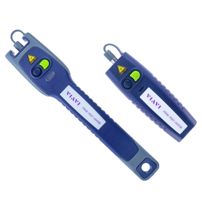
Visual Fault Locators
Visual fault locators for fiber bends and breaks, localization of damages and end-to-end continuity check.
-

P5000i Fiber Microscope
Automated Fiber Inspection & Analysis Probe provides PASS/FAIL capability to PC, laptops, mobile devices and...
-

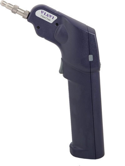
FiberChek Probe Microscope
The "all-in-one" handheld solution for fiber inspection.
-

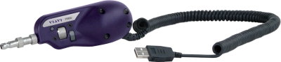
MP-60/-80 Miniature USB 2.0 Power Meters
Measures optical power via a USB 2.0 connection to a PC/laptop/smart device - makes digital processing of optical...
-

SmartPocket V2 OLP-35V2/-35SC/-38V2 Broadband Power Meters
A family of pocket-sized and low-cost optical power meters for the installation and maintenance of single mode and...
-

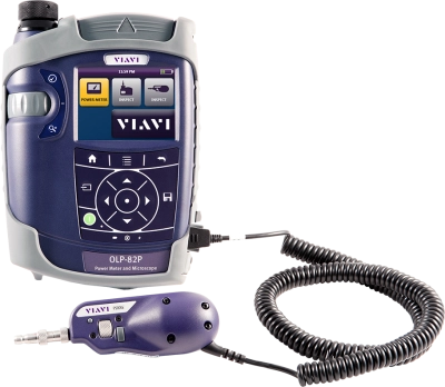
SmartClass Fiber OLP-82/-82P Inspection-Ready Optical Power Meters
Designed for the installation and maintenance of single mode and multimode fiber optic networks. Combine pass/fail...
-

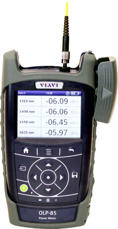
SmartClass Fiber OLP-85/-85P Inspection-Ready Optical Power Meters
With a 100 dB dynamic range, the OLP-85 and -85P are perfect for any fiber-optic network power or loss test...
")

")
")


-

SmartPocket V2 OLS Optical Light Sources
A family of pocket-sized and low-cost optical light sources for the installation and maintenance of single mode and...
-

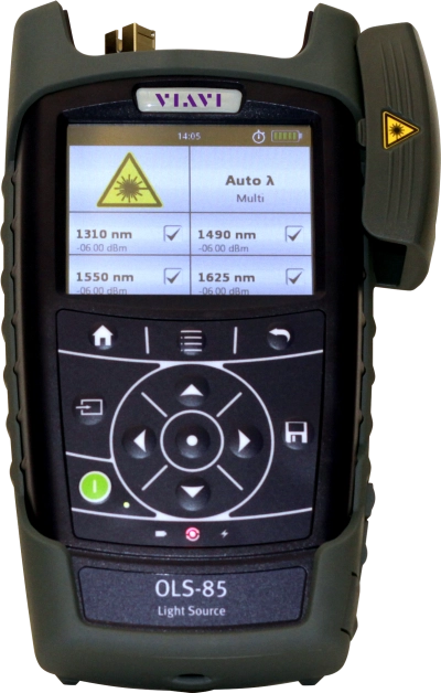
SmartClass Fiber OLS-85 Inspection-Ready Optical Light Sources
The OLS-85 inspection-ready optical light source is the ideal partner to the SmartClass Fiber OLP-85 and OLP-85P to...
-

SmartPocket V2 OMK-35V2/-36V2/-38V2 Optical Test Kits
A family of pocket-sized and low-cost optical power meter plus optical light source kits for the installation and...
-

SmartClass Fiber ORL-85 Inspection-Ready Optical Return Loss Meters
The SmartClass Fiber ORL-85 combines optical power meter (OPM), light source (OLS), continuous wave return loss...
-

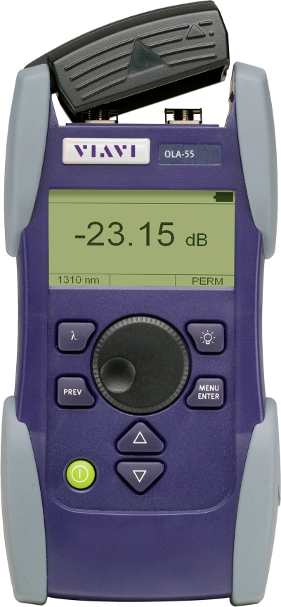
SmartClass OLA-54/-55/-55M Optical Level Attenuators
Compact and rugged handheld attenuators for field or lab use.


Fiber Optic Testers for Every Technician
The VIAVI essential fiber testers lead the industry in helping technicians ensure best practices for handling fiber in every situation, from certifying new fiber installations to troubleshooting active fiber networks. Through technology innovation and extensive experience, our fiber testers equip technicians and network managers to ensure the performance of their fiber optic networks with fast and intuitive fiber testers that are essential for every technician. Learn more about fiber inspection and fiber testing.
Essential Fiber Testers
- Our industry-leading fiber optic inspection scopes provide handheld solutions with all the necessary capabilities that fiber technicians need for today’s fiber testing and inspection requirements; including live image viewing, auto-center, auto-focus, PASS/FAIL analysis, and storing/recalling/sharing results.
- Innovative optical power meters that eliminate common hassles when measuring optical power, giving technicians a fast, compact and safe solution for optical power measurement.
- Our free mobile app makes it even easier to perform essential fiber testing by allowing technicians to inspect fiber end-face quality, measure optical power, and certify fiber connectors to industry standards right on their mobile device.
- Efficient and economical visual fault locator for fiber tracing, fiber routing, and fiber continuity checking in an optical network during and after installation.
Support at Every Step
We provide support, services, comprehensive training and the resources you need. It’s all part of what we do to maximize the value of your VIAVI investment.
Ask an Expert
Contact us for more information or to receive a price quote. We have the experts to give you the right answer on any of your questions.