What is Software Defined Radio (SDR)?
Learn all about software defined radio and systems, and take a deep dive into application domains.
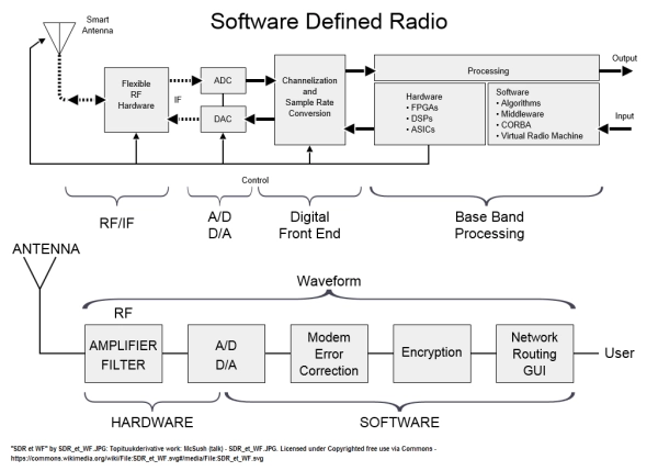
Software Defined Radio (SDR) is commonly defined as a “Radio in which some or all of the physical layer functions are software defined”. SDR technology uses software, instead of conventional hardware, to perform radio-signal processing functions. Filters, error correction, synchronizers, modulators/demodulators, and frequency tuners used in conventional systems can all be written in software. Software defined devices can be reconfigured to adapt to changing product requirements.
While the term SDR refers to radio systems, the concept of processing signals in software rather than through hardware components is applicable to many more systems such as Radar, Automobile, Robotics, Electronic Warfare. A more generic term could be Software Defined Systems, or SDS.
SDRs work much like desktop computing where a single hardware platform can carry out many functions based on the software applications loaded. SDRs use high-speed reprogrammable devices such as Digital Signal Processors (DSPs), Field Programmable Gate Arrays (FPGAs), or General Purpose Processors (GPPs), executing tasks performed by hardware in conventional radio systems.
The system’s software-based filtering algorithms configure radio parameters such as operating modes, frequency, and modulation, eliminating the need for hardware components such as mixers, filters, amplifiers, modulators, and demodulators. This type of design results in a radio which can receive and transmit different radio protocols simply by changing software, providing the flexibility needed to efficiently use the radio frequency spectrum and expand a radio’s capabilities without the need for hardware updates.
SDR technology addresses the exponential growth by which people need to communicate. Data, voice, video, messaging, command and control, emergency response communications, etc. are all encompassing communication mechanisms currently within the SDR domain. SDR is a solution to competing demands about providing greater access to communication means while keeping a tap on the equipment costs. SDR is a flexible and cost-efficient solution where benefits can be realized by service providers, product developers and even reaching end users.
Contact a VIAVI expert for more information about software defined systems and VIAVI SDR products.
Below are several key features and benefits of using SDR:
- Reduce development cost and time to market by integrating software blocks rather than hardware redesign
- Reduce innovation cycle
- Protection against hardware obsolescence
- In-field updates/upgrade of system capability via software download
- Single hardware platform can support multiple communications protocols via software application loads
- Multi-purpose platform supporting multiple application domains (e.g. Radio/EW)
- Development of domain specific applications can be initiated on personal computers or COTS platform
- COTS eco-system to simplify the software development can be used
The flexibility provided by SDR makes the technology a logical choice to meet the ever-changing requirements of today’s commercial and military products. While the term SDR refers to radio systems, the concept of processing signals in software rather than through hardware components is applicable to many more systems such as Radar, Automobile, Robotics, Electronic Warfare. A more generic term could be Software Defined Systems, or SDS.
Test & Measurement Instruments
As software-defined radios (SDRs) are being more widely deployed, test and measurement instruments are ramping up to be able to test SDRs in a way that was not possible before. The market is moving so fast, manufacturers need to be able to react quickly.
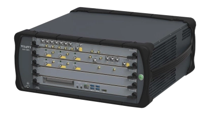
In many cases, the products and protocols under test are evolving or still being defined until very late in the product development life-cycle. Supporting all the changes in hardware is very expensive and far too slow. In fact, traditional testers are often obsolete by the time they are brought to market. Software-defined testers (also known as virtual instruments) provide the level of flexibility required to adjust as the standards and protocols evolve. Furthermore, next-generation software-defined instruments allow engineers to peek inside the radios to monitor and alter internal signals of the waveform. Not being constrained to the antenna port (i.e. black box testing) provides an unprecedented way of testing and qualifying radios.
The Software Communications Architecture (SCA) allows that flexibility by offering standardized interfaces which can be used to implement Test Probes for monitoring or injecting signals to SCA components. This makes SCA, a perfect candidate to be used in the Test and Instrumentation domain.
Radar
Radar systems must perform massive signal analysis to convert information, collected by the antennas, into some form accessible by the user, be it an air traffic controller, weather monitoring or an embedded computer autonomously controlling a larger system (cars, robots, drones). Current state-of-the art radars perform this analysis by exploiting the capabilities of modern digital processors.

The microwave signal is digitized and fed to one, many, or a combination of Field Programmable Gate Arrays (FPGAs), Digital Signal Processors (DSPs), Graphics processing units (GPUs), or General Purpose Processors (GPPs) where it will be filtered, down-converted, weighted, delayed, combined, and passed through many other algorithms to obtain the desired information with the required accuracy. Those digitally processing radars are dubbed Software Defined Radars, by analogy to the Software Defined Radios that are now being commonly used in the military and commercial sectors.
The mere fact that the signal processing is now performed in the digital domain provides a huge advantage over the older and more traditional all-RF implementations. The processing algorithms can be modified faster and easier in software than in an all-hardware implementation. Depending on the application scenario, transmit and receive signal processing functions can be adapted on demand to suit requirements. New functionalities can be added without the need to upgrade or replace hardware components. Maintenance costs can decrease as the system can be upgraded or fixed on-site.
This flexibility comes at a cost, trading hardware inflexibility by added software complexity. Code generation and debugging is increasingly complex, not only due to the number of algorithms that must now be programmed, but also due to the distributed and heterogeneous nature of the hardware processing platforms required for radar applications. Nowadays, it is not uncommon to find applications that make combined use of GPPs, DSPs, and FPGAs (some even using GPUs) where the application software is partitioned, deployed, and configured across such distributed heterogeneous processors.

Software integration thus becomes, in some cases, a major source of cost overrun. Not to mention that often most of the software-related work will need to be redone from the beginning with every new generation of the product, as the hardware platform changes.
With the growth of the software size and complexity, the traditional approach to software development is increasingly inefficient, leading to lower productivity and consequently higher cost.
An approach to improve on this has been developed and adopted by military organizations for their communications systems. Under the joint efforts of US Department of Defense (DoD)’s Joint Tactical Networking Center (JTNC) (erstwhile JTRS) and the Wireless Innovation Forum (WInnF) (SDR Forum v2.0), a system design architecture framework has been developed promoting software portability and reuse, facilitating hardware upgrades and overall system scalability in an attempt to reduce development time and cost of new products. The software architecture, called Software Communications Architecture (SCA), has been adopted by the major Armed Forces around the world, and is now used by the major military radio manufacturers. The SCA promotes software portability and reuse to address software size and complexity growth in the Radar domain.
Electronic Warfare
Electronic Warfare (EW) capabilities are becoming invaluable necessities in combat situations. Advanced warning, searching, intercepting, locating, recording, detection and target acquisition are indispensable tasks in EW.

Combat scenarios are changing due to new threats being developed while defenses are being tested with the aid of the electromagnetic spectrum. In EW the need to gather, validate and process data from many different sources is a must. Identifying what electronic emitters are up to – whether friendly, hostile, or unidentified – is crucial for effective electronic warfare operations. Decisions need to be made quickly with such acquired intelligence. Mission success now requires a comprehensive knowledge of the electronic battlespace.
When searching for potential threats, microwave signals are digitized and fed to one, many, or a combination of Field Programmable Gate Arrays (FPGAs), Digital Signal Processors (DSPs), Graphics processing Units (GPUs), or General-Purpose Processors (GPPs). The signals are then filtered, down-converted, weighted, delayed, combined, and passed through many other algorithms to obtain the desired information with the required accuracy.
The main challenges in EW include signal detection, emitter parameter measurement and correlation, emitter sorting, identification, and operator notification, which are often classified as Electronic Support Measures (ESM) or Radar Warning Receiver (RWR) systems. ESM systems are often tasked to preserve electronic data for future analysis. Traditionally, ESM systems focus on emitters locations with the support of RWRs that estimate position/distance.
A non-comprehensive lists of a typical emitter characteristics, that ESM system functions can measure, includes radio frequency, amplitude, direction of arrival, time of arrival, pulse repetition interval, pulse width, scan type and rate and lobe duration (beam width). Other advanced ESM systems can also measure pulse repetition interval modulation characteristics, inter-and intra-pulse frequency modulation (FM), missile guidance characteristics, and continuous wave signals.
By relying on a collection of algorithm implementations mostly done in software, EW is part of a larger trend of Software Defined domains that are looking into component-based architectures with enhanced portability and reuse of algorithm implementations. For large organizations that work on EW, Software Defined Radios, Software Defined Radars, etc., the benefits are multiplied as algorithm implementations can be shared as software components across those multiple domains.
The Software Communications Architecture (SCA) follows a Component Based Development (CBD) paradigm that provides a framework for software components reuse that is highly suited for the EW domain.
Robotics & Automation
Historically and traditionally the communications facilities and autonomous capabilities of an unmanned system have been completely independent. Communications and autonomy were stove piped sub-systems whose only interface was a port through which binary data was sent to the radio for transmission and received from the radio for processing.

Advances in technologies have significantly changed the way radios are built, to the point where it is no longer just hardware that modulates and demodulates waveforms. The Software Defined Radio (SDR) paradigm is on the leading edge of radio technology, using software to implement most of the radio functionality, including the modulation and demodulation of waveforms. With its software underpinning, the SDR is an extremely flexible device whose performance characteristics can be easily modified via a software update. With such a large degree of flexibility, as is offered by a software approach, the question then becomes how to implement a SDR and how to ensure radio compatibility.
These questions of implementation and standards are addressed by the Software Communications Architecture (SCA), which is the defining standard for the U.S. Army’s Joint Tactical Radio Systems (JTRS) and is being adopted throughout the world for national SDR programs for countries in Europe, Asia, the Middle East and South America. The SCA responds to the challenges of implementing sophisticated radio control and algorithms by adopting the Component Based Software Engineering (CBSE) paradigm that provides a formalized approach to address the complexity problem.
Given that the robotics community has also adopted the same CBSE approach to deal with software complexity, a strong convergence exists between the communications and autonomy capabilities of an unmanned system. More specifically, it is now not only possible, but also desirable, to integrate autonomous capabilities with radio communications functionality. Integration onto a single hardware system offers several potential advantages:

- Reduced implementation complexity
- Weight savings
- Lower overall power consumption
- Increased flexibility, portability, reusability, and expandability
- Opportunities to optimize radio communications
Both the required hardware and software architecture/framework now exist that allows for the close integration of radio communications and autonomy capabilities into a single processor. The software development process can be expedited using commercially available graphical modeling Integrated Development Environments (IDEs) that greatly simplify the development of software components that implement core radio and autonomy capabilities. Those software components are then taken into the autonomous system and executed via the SCA Core Framework, which is a standardized deployment engine of software components for Heterogeneous Embedded Distributed Systems (HEDS).
It is no longer necessary to consider unmanned system radio communications and autonomy capabilities as separate stove piped systems. Technology is now available that allows for the close integration of the formerly independent sub-systems. With this close integration the autonomy software can influence the radio configuration and vice versa. The advantages to such an approach are numerous and will assist the designer/engineer in producing ever more capable unmanned systems that are more flexible and expandable than currently fielded products.
Software Architecture
Software Defined Systems (SDS) provide the flexibility to be reconfigured to adapt to changing environment and requirements. Not surprising that software has become the largest component of electronic systems today demanding more development resources than hardware. However, as the underlying electronic becomes more complex with the rapid evolution of processors and heterogeneous nature of embedded systems, developing software has also become a challenge. Conventional approaches whereby software applications are tightly coupled with the processing hardware is no longer acceptable. Any modification to the hardware (product evolution, obsolescence, third party technology insertion) requires significant adaptation which are prone to errors and time consuming. A paradigm shift is required in the development of software for Heterogeneous Embedded and Distributed Systems (HEDS). Military systems must be much more responsive to adapt to the constant and rapid evolution of opponent’s systems.
There is, therefore, a need for a paradigm shift in the software development process that will enable greater design flexibility and speedup the introduction of innovations, extend the lifetime of products and reduce the overall lifecycle cost. The international community developing military communications systems have tackled this issue under the leadership of the US Department of Defense and the Wireless Innovation Forum and have developed an open standard for the development of software that promotes portability between platforms and reusability of software to facilitate interoperability and reduce development cost and time-to-market. Today, over 500,000 military radios have been fielded based on the Software Communications Architecture.
The VIAVI eCo Suite offers users the advantage of building SCA-based Software Defined Systems (SDS) like Software Defined Radios (SDR). And the videos in this section answer all the questions and concerns of HEDS development based on the SCA that can affect the success of your SDS.
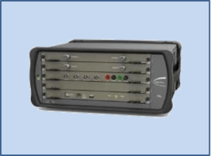
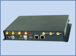
The proposed SDR lab is built around four categories of platforms each having specific characteristics that together offer a good representation of the operational environment.
Questions?
- If you have any questions about our products and services please contact us at +1-819-307-0333 or email us at info.SCA@viavisolutions.com
