What is OTDR Testing?
Learn to certify, maintain, and troubleshoot your fiber optic systems better with industry-leading OTDR test equipment and procedures.
With the rapid advancements in fiber optic technology and new fiber network deployments, OTDR testing methods have become indispensable for building, certifying, maintaining, and troubleshooting fiber optic systems.
An Optical Time Domain Reflectometer (OTDR) is an instrument used to measure and create a visual representation of a fiber optic cable route. The measurement data can provide information on the condition and performance of fibers, as well as any passive optical components along the cable path like connectors, splices, splitters and multiplexers.

Once this information has been captured, analyzed, and stored, it can be recalled as needed to evaluate the same cable over time.
Troubleshoot Fiber Optic Cable Failures with OTDRs
The OTDR is also the only fiber testing tool capable of troubleshooting fiber optic cable failures by locating the distance to the fault and identifying the type and cause of the fault, including breaks, bends, bad connectors, and any excessive insertion loss “events”. To do this an OTDR uses the effects of Rayleigh scattering and Fresnel reflection to measure the condition of a fiber link, and while single-ended (uni-directional) tests can be performed, dual-ended bidirectional OTDR testing improves measurement accuracy event detection and is required in order to comply with the IEC and ITU-T testing standards.
OTDR Form Factors
An OTDR instrument can be portable for transport from site to site or rack-mounted for permanent placement and monitoring of a network with alarms triggered automatically if the fiber is compromised.
Predictive OTDR Measurements
Along with the Rayleigh scattering method used to characterize fiber links, OTDR can also use Raman and Brillouin scattering effects to predict breaks, monitor fiber health, and prevent service outages through temperature and strain measurements. These three techniques form a powerful combination for managing fiber cabling networks or utilizing the fiber for Distributed Fiber Optic Sensing.
Although originally intended for long haul fiber optic applications, newer generation high resolution OTDR tools can also be used to diagnose much shorter cables, such as internal aircraft and enterprise facility cabling such as structured cabling. Multiple-pulse measurement or acquisition techniques have also been developed to test more complicated configurations, including PON networks and fiber to the home (FTTH) deployments.
Contact sales to learn more about VIAVI OTDR Testing Equipment today, or use the OTDR selector tool to find the recommended tool and request an OTDR price quote.
How Does an OTDR Work?
The OTDR sends a pulse of light energy (optical power), generated by a laser diode, into one end of an optical fiber. A photodiode measures the returning light energy or optical power reflected and scattered back (backscattered) over time and converts it into a measurement value that is displayed as a graph (or trace) on a screen.
The location of each event and the overall cable length are calculated based on the round-trip time of the light pulse traveling through the fiber core and the reflected/backscattered light returning to the OTDR detector. The insertion loss is calculated from the proportional amplitude change of the reflected/backscattered light.
Many modern OTDR tools automatically select the optimal acquisition parameters for a particular fiber by sending out test pulses in a process known as auto-configuration, auto setup, or auto test. Despite advanced technology that now allows many OTDR test systems to automatically determine the best settings, it is still important to understand what the underlying settings are and how they may impact your results.
OTDR Testing Analogy
There are obvious comparisons between OTDR and the copper wire testing equivalent, TDR, which it has gradually replaced, as they are both based on Time Domain Reflectometry. Another useful analogy can be found with Ultrasound technology.
In medical imaging applications, high frequency (≥20KHz) inaudible sound waves are produced by the vibrating elements of an ultrasound transducer. Sound waves reflected back to the source allow the creation of accurate images of bodily features. In much the same way, the reflected or scattered light from the OTDR test pulse allow the overall condition of the fiber core to be “seen”.
Understanding the science behind OTDR begins with a few basic concepts that are important to the OTDR testing process.
Attenuation
The reduction in optical power of the light signal as it is transmitted. Fiber attenuation is expressed in decibels per kilometer (dB/km). The degradation in a transmitted light signal may be due to bending, splices, connectors/connections, or the absorption and scattering properties of the fiber itself. See VIAVI attenuators.
Backscatter
A term used to describe the dispersed reflection of light back in the direction from which they originated. The amount of backscatter is one indicator of total fiber attenuation, since light traveling back to the source represents a loss in downstream signal intensity. In OTDR testing, for ‘healthy’ fiber the amount of backscattered light is only about one-millionth of the test pulse.
Reflectance
A measure of the proportion of light reflected by abrupt changes in material density. Connectors/connections, air gaps and breaks will reflect light back, allowing the OTDR to determine the position, condition, and signal loss from these components/events. The magnitude of a reflection will depend upon the degree of change in the index of refraction.
Refraction
Refraction is the bending of light waves as they pass from one transparent material type to another. The amount of light reflected is determined by the differences in the index of refraction of two fibers and is mostly an issue associated with connectors but can also effect mechanical splices where an index matching gel is used.
OTDR Testing Process
Performing an OTDR test requires some basic setup, programming, test execution, and reporting processes to be followed.
- Power on the OTDR and verify the battery is charged and the test display is functioning.
- Clean and inspect the ends of all fibers under test, launch cables, connectors, and adapters.
- Carefully connect the launch cable to the test port of the OTDR at one end and the fiber under test at the opposite end.
- Select a pre-programmed test configuration (or setup), based on the network type and test conditions, or set/adjust the test parameters as necessary. Manual OTDR test parameter settings typically include the following:
- Range: Sets appropriate range (distance) based on the overall fiber length
- Pulse Width: Sets the duration of each laser pulse emitted
- Acquisition Time: Sets the time duration for averaging the measurements of reflected light
- Refractive Index: Adjusts for the index of the cable material being tested
- Loss threshold settings for the system and individual elements or “events”
- Initiate the OTDR acquisition to obtain the test results and graphical “trace”
- Store and/or upload test results as necessary
- Carefully disconnect all cables, connectors, and adapters
OTDR Best Practices
Before launch or reference cables and the fiber under test are connected for measurement, fiber cleaning and inspection practices are of the upmost importance. Learn more about the VIAVI Inspect Before You Connect methodology on our Fiber Inspection page.
Mating connectors between launch cables, the fiber under test, and OTDR must be compatible to minimize reflectance. Imagine a hose bib with a loose or crooked connection to the hose itself, causing water to leak and spray backwards from the junction. This is similar to the impact of an incorrect OTDR connection, when air gaps allow too much light to be reflected back and overload the photodiode.
The use of a receive cable at the far end of the fiber under test is another recommended best practice and specified in the IEC and ITU-T test standards in order to accurately measure the end connector. To measure and qualify a connector it must be mated with another connector so that when an OTDR test is performed light passes through the connector end face into the end face of the receiving mated connector and receiving fiber, providing an optical linkage that allows losses to be measured for the end connector.
Learn more about fiber characterization.
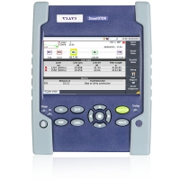
The best handheld OTDR tools include features for one touch operation and applications tailored for different skill levels and network types. The VIAVI SmartOTDR Handheld Fiber Tester delivers improved productivity with automated pass/fail test results.
Interpreting the OTDR Test Results
Once the OTDR test is completed, the instrument will display the OTDR results in both numeric and graphical formats. The graph, also called a trace, will show where each connector/connection, splice, bend or break is located, along with the signal loss (in dB) and reflection characteristics of each element.
Advanced VIAVI OTDR test equipment with features like SmartLink Mapper (SLM) also translate this trace data into an icon based linear view where each element and event is represented as an easy-to-read icon, with pass/fail information visible immediately, and the name of each component/event clearly shown. SmartLink Mapper also provides customized applications and icons for applications like FTTH, PON networks, or Fiber to the Antenna (FTTA).
The overall fiber length and link loss are displayed once a test run is completed. If loss thresholds were initially set, Pass or Fail will be indicated for each element of the fiber link.
Although feature sets, size, and cost vary significantly, there are three main categories of OTDR test equipment available on the market today.
- Benchtop
This term typically describes the OTDR test equipment used in laboratories and production facilities. Benchtop devices can be placed on a laboratory workbench or in a production test bay, and usually have a larger display, more available expansion ports for applications like MPO testing, and a direct AC (outlet) power source. Benchtop OTDR test equipment may be used when a high level of accuracy, sensitivity or long-range measurement (with its inherent high power pulse intensity) is required. - Hand-held OTDR
As the name implies, hand-held OTDR test equipment is lightweight (less than 1kg), portable, typically battery-powered, and optimized for use in the field. The user interface is usually simple and straightforward so that technicians can easily learn to operate the OTDR. Hand-held OTDR meters can also integrate additional tools needed for fiber certification and troubleshooting, such as Visual Fault Locators (VFL), Optical Power Meters (OPM), and compact fiber inspection microscopes. Connectivity options including Wi-Fi or Bluetooth can be used to transfer test results and work orders quickly. - Embedded or Rack-Mounted OTDR
Embedded OTDRs are designed and manufactured with a small form factor that can be integrated easily within network monitoring equipment. Rack-mounted OTDRs are combined with an optical switch to automatically rotate across many fibers. A programmed test routine can prioritize critical fibers and important customers. These fiber monitoring applications can be used for either in-service or dark fiber monitoring.
OTDR specifications are important to understand so one can choose the right OTDR for a dedicated application.
- Dynamic range
Expressed in decibels (db), the dynamic range is defined as the difference between the initial power level reflected from the fiber when set to maximum pulse width and the upper level of the noise floor of the detector. The dynamic range determines the maximum observable length of a fiber. - Event dead zone
The event dead zone (EDZ) is the minimum distance that the OTDR can detect between two reflective events (typically two connections). In the case where the reflective events are more closely spaced than the EDZ, the OTDR will show them as one event. - Attenuation dead zone
The attenuation dead zone (ADZ) defined in the IEC 61745 standard is the minimum distance after a reflective (e.g. connector) or attenuation (e.g. splice) event, where a non-reflective event (splice) can be measured. Much like the EDZ, the ADZ is dependent on the pulse width. - Wavelengths
An OTDR sends a pulse of light based on to the wavelength(s) used for transmission when the fiber link is operational. The typical wavelengths are 850 nm and 1300 nm for multimode fiber and 1310 nm, 1550 nm and 1625 nm for single-mode fiber. Filtered 1625 nm or 1650 nm wavelengths can be used for in-service maintenance testing to avoid interference with the live traffic wavelengths.
OTDR Manufacturers
By supporting the fastest-growing segment of the fiber testing market, OTDR equipment manufacturers have experienced ongoing expansion worldwide in all product categories, and this trend is expected to continue. 5G adoption is bringing new opportunities and challenges, with fiber monitoring, installation, and manufacturing operations all reacting to the ongoing demand. As an industry leading OTDR manufacturer, VIAVI is addressing the unprecedented customer requirements for OTDR safety, efficiency, and test product quality.
Calibrating OTDR Test Equipment
For all measurement equipment, periodic calibration is necessary to measure and correct equipment bias and reset functions based on reference standards. In industries where the accuracy of OTDR test results is essential, the IEC 61746 standard for calibration, as well as the TIA/EIA-455-226 standard (adopted from the IEC standard) are recognized.
The IEC standard includes specific practices for calibrating point-to-point accuracy, linearity, attenuation, power output and delay. Given the complexity, OTDR calibration is best left to OTDR equipment manufacturers or certified calibration labs.
The Future of OTDR Testing
Providing more functionality, accuracy, and resolution at a lower price point is an ongoing challenge. Improvement in OTDR auto test algorithms is continuing to lower the barrier of entry for technicians and increase acceptance.
Without technology such as OTDR testing, advanced application of fiber optics would not be feasible. The ability to “see” inside thousands of miles of optical fiber no thicker than a human hair has become both an incredible accomplishment and a practical necessity.
Over the next decade, new 5G networks carrying massive data loads, smart cities connected through communication networks, and the ongoing deployment of FTTH services will ratchet the industry demand for efficient, versatile, OTDR testing. With breakthrough OTDR innovations like SmartLink Mapper and Smart Acquisition making testing easier, more accurate, and more powerful, VIAVI is addressing the fiber installation and maintenance needs of the future.
OTDR Testing Blogs
- Fiber Testing — Get The Right Perspective
- Why Perform Bidirectional Fiber Testing?
- What the Standards Say About Bidirectional OTDR Testing